Showing posts with label Hackaday. Show all posts

Friday, November 13

“Artificial Sun” Lighting Via Old Satellite Dishes

Real sunlight is a beautiful thing, but due to the vagaries of Earth’s orbit and local weather systems, it’s not available all the time. [Matt] decided this wasn’t good enough, and set about building a rig to replicate the sun’s rays as closely as possible.

Rayleigh scattering is emulated by passing the light through a glass chamber filled with soapy water – taking advantage of the Tyndall effect.

The great distance between the Sun and the Earth means that the sun’s rays are essentially parallel from our local vantage point. Replicating this, and the soothing nature of a blue sky, were [Matt]’s primary goals with the project. To achieve this, an old satellite dish was pressed into service as a parabolic reflector, coated with mirror-finish vinyl strips. A 500W white LED with a good color rendering index was fitted at the focal point, outfitted with a water cooling system to shed heat. With a point source at its focal point, the parabolic reflector bounces the light such that it the rays are parallel, giving the sense that the light source is coming from an effectivelyl infinite distance away. To then achieve the blue sky effect, the light was then passed through a glass chamber filled with soapy water, which scatters the light using the Tyndall effect. This mimics the Rayleigh scattering in Earth’s atmosphere.

The final result is amazing, with [Matt] shooting footage that appears to be filmed in genuine daylight – despite being shot at night or on rainy days. He also features a cutdown build that can be achieved in a far cheaper and compact form, using Fresnel lenses and blue film. We’ve featured [Matt]’s daylight experiments before, though we’re amazed at the new level reached. Video after the break.

Fran Finds Four Foot Alphanumeric Displays From 1910

Video blogger and display technology guru [Fran Blanche] has discovered a splendid retro-tech alphanumeric display from 1910. (Video, embedded below.)

We have always enjoyed her forays into old and unusual displays, including her project researching and reverse engineering an Apollo DSKY unit. This time [Fran] has dug up an amazing billboard from the early 20th century. It was built by the Rice Electric Display Company of Dayton Ohio, and operated in Herald Square for about two years. Requiring $400,000 in 1910-US-dollars to build, this was clearly an Herculean effort for its day and no doubt is the first example of selling advertising time on a computer-controller billboard. It boasts characters that are about 1.3 m tall and 1 m wide which can display letters, numbers, and various punctuation and symbols. These are arrayed into a 3-line 18-character matrix that is about 27 x 4 meters, and that’s up only a third of the total billboard, itself an illuminated and dynamic work of art.

Diagram Depicting the 3×18 Character Display

There are quite a few tantalizing details in the video, but a few that jumped out at us are the 20,000 light bulbs, the 40 Hz display update rate, the 150 km of wire used and the three month long installation time. We would really like to learn more about these two 7.5 kW motorized switch controllers, how were they programmed, how were the character segments arranged, what were their shapes?

In the video, you can see triangles arranged in some pattern not unlike more modern sixteen segment displays, although as [Fran] points out, Mr Rice’s characters are more pleasing. We hope [Fran] can tease out more details for a future video. If you have any ideas or knowledge about this display, please put them in the comments section below. Spoiler alert after the video…

…this display is no longer standing.

DSP Spreadsheet: The Goertzel Algorithm is Fourier’s Simpler Cousin

You probably have at least a nodding familiarity with the Fourier transform, a mathematical process for transforming a time-domain signal into a frequency domain signal. In particular, for computers, we don’t really have a nice equation so we use the discrete version of the transform which takes a series of measurements at regular intervals. If you need to understand the entire frequency spectrum of a signal or you want to filter portions of the signal, this is definitely the tool for the job. However, sometimes it is more than you need.

For example, consider tuning a guitar string. You only need to know if one frequency is present or if it isn’t. If you are decoding TouchTones, you only need to know if two of eight frequencies are present. You don’t care about anything else.

A Fourier transform can do either of those jobs. But if you go that route you are going to do a lot of math to compute things you don’t care about just so you can pick out the one or two pieces you do care about. That’s the idea behind the Goertzel. It is essentially a fast Fourier transform algorithm stripped down to compute just one frequency band of interest.  The math is much easier and you can usually implement it faster and smaller than a full transform, even on small CPUs.

Fourier in Review

Just to review, a typical system that uses a Fourier transform will read a number of samples at some clock frequency using an analog to digital converter. For example, you might read 1024 samples at 1 MHz. Each sample will be 1 microsecond after the previous sample, and you’ll get just over a millisecond’s worth of data.

The transform will also produce 1024 results, often known as buckets. Each bucket will represent 1/1024 of the 1 MHz. Because of the Nyquist limit, the top half of the results are not very useful, so realistically, the first 512 buckets will represent 0 Hz to 500 Hz.

Here’s a spreadsheet (after all, this is the DSP Spreadsheet series of articles) that uses the XLMiner Analysis Addon to do Fourier transforms. The sample frequency is 1024Hz so each bucket (column G) is worth 1 Hz. Column B generates two sine waves together at 100 Hz and 20 Hz. We talked about generating signals like this last year.

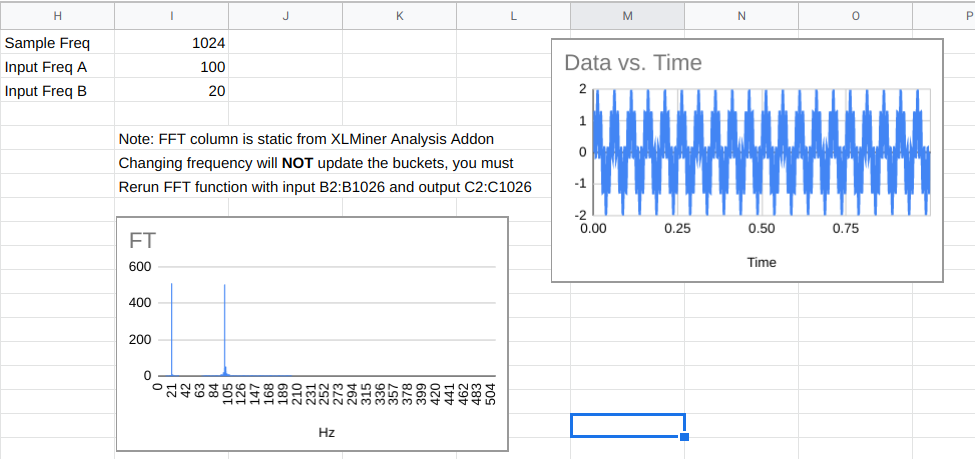
The FFT data in column C are complex numbers and they do not update live. You have to use the XLMiner add on to recompute it if you change frequencies. The magnitude of the numbers appear in column F and you’ll see that the buckets that correspond to the two input frequencies will be much higher than the other buckets.

One Bucket of Many

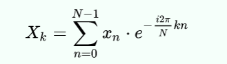
If our goal was to find out if the signal contained the 100 Hz signal, we could just compute cell F102, if we knew how. That’s exactly what the Goertzel does. Here’s the actual formula for each bucket in a discrete Fourier transform (courtesy of Wikipedia):

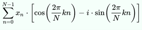
If you apply Euler’s formula you get:

Mathematically, N is the block size, k is the bucket number of interest, xn is the nth sample. Since n varies from 0 to N-1, you can see this expression uses all of the data to compute each bucket’s value.

The trick, then, is to find the minimum number of steps we need to compute just one bucket. Keep in mind that for a full transform, you have to do this math for each bucket. Here we only need to do it for one. However, you do have to sum up everything.

Cut to the Chase

If you do a bit of manipulation, you can reduce it to the following steps:

  1. Precompute the frequency ratio in radians which is 2Πk/N
  2. Compute the cosine of the value you found in step 1 (call this C); also compute the sine (call this S)
  3. For each bucket in sequence, take the value of the previous bucket (P) and the bucket before that (R) and compute bucket=2*C*P-R and then add the current input value
  4. Now the last bucket will be set up to nearly give you the value for the kth bucket. To find the real part, multiply the final bucket by C and subtract P. For the imaginary part, multiply S times the final bucket value
  5. Now you want to find the magnitude of the complex number formed by the real and imaginary parts. That’s easy to do if you convert to polar notation (find the hypotenuse of the triangle formed by the real and imaginary part).

Of course, there’s a spreadsheet for this, too. With the limitations of a spreadsheet, it does a lot of extra calculations, so to make up for it, column D hides all the rows that don’t matter. In a real program you would simply not do those calculations (columns E-G) except for the last time through the loop (that is, on each row). You need a few samples to prime the pump, so the first two rows are grayed out.

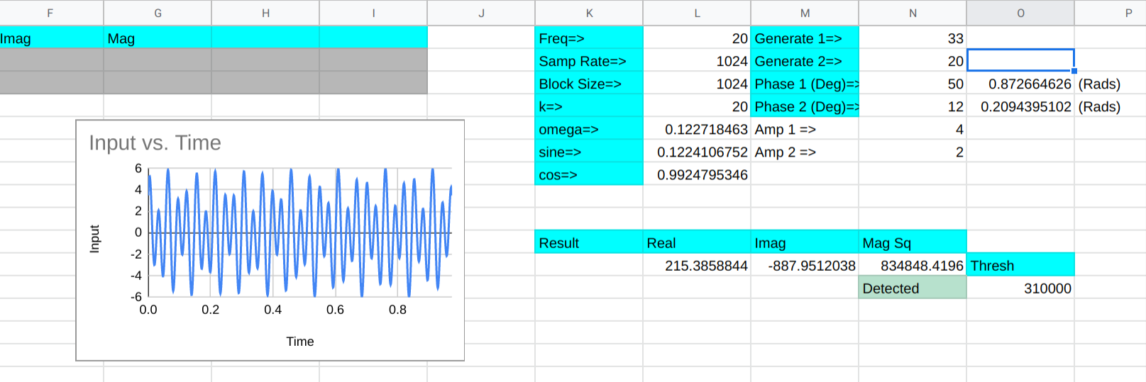
There are other optimizations you’d make, too. For example, the cosine term is doubled each time through the loop but not on the final calculation. In a real program, you’d do that calculation once, but for a small spreadsheet, there’s not much difference.

Column B is the input data, of course. Column C is the running total of the buckets. Columns E-G on the last row represents the final computations to get the bucket k’s complex result. The real place to look for the results in around L11. That part of row 11 picks up the one visible part of columns E-G and also squares the magnitude since we are looking for power. There’s also a threshold and a cell that tells you if the frequency (at L1) is present or not.

Try changing the generated frequencies and you’ll see that it does a good job of detecting frequencies near 20 Hz. You can adjust the threshold to get a tighter or broader response, but the difference between 20 Hz and 19 or 21 Hz is pretty marked.

Real Code

Since a spreadsheet doesn’t really give you a feel for how you’d really do this in a conventional programming language here is some pseudo-code:


omega_r = cos(2.0*pi*k/N);
omega_r2=2*omega_r;
omega_i = sin(2.0*pi*k/N);

P = 0.0;
S = 0.0;
for (n=0; n<N; ++n)
{
   y = x(n) + omega_r2*P -S;
   S = P;
   P = y;
}
realy = omega_r*P - S; // note that hear P=last result and S is the one before
imagy=omega_i*P;
magy=abs(complex(realy,imagy));  // mag=sqrt(r^2+i^2);

Since you can precompute everything outside of the loop, this is pretty easy to formulate in even a simple processor. You could even skip the square root if you are only making comparisons and want to square the result anyway.

Tradeoffs

Don’t forget, everything is a tradeoff. The sampling rate and the number of samples determine how long it takes to read each sample and also how broad the frequency range for the bucket is. If you are having to probe for lots of frequencies, you might be better off with a well-implemented Fourier transform library.

There are other ways to optimize both algorithms. For example, you can limit the amount of data you process by selecting the right sample rate and block size. Or, instead of using a Fourier transform, consider a Hartley transform which doesn’t use complex numbers.

In Practice

I doubt very seriously anyone needs to do this kind of logic in a spreadsheet. But like the other DSP spreadsheet models, it is very easy to examine and experiment with the algorithm laid out this way. Developing intuition about algorithms is at least as important as the rote recollection of them — maybe it is even more important.

The Goertzel is an easy way to sidestep a more complicated algorithm for many common cases. It is a tool you should have in your box of tricks.

Hackaday Podcast 093: Hot and Fast Raspberry Pi, Dr. Seuss Drone, M&M Mass Meter, and FPGA Tape Backup

Hackaday editors Mike Szczys and Elliot Williams wrangle the epic hacks that crossed our screens this week. Elliot ran deep on overclocking all three flavors of the Raspberry Pi 4 this week and discovered that heat sinks rule the day. Mike exposes his deep love of candy-coated chocolates while drooling over a machine that can detect when the legume is missing from a peanut M&M. Core memory is so much more fun when LEDs come to play, one tiny wheel is the power-saving secret for a very strange multirotor drone, and there’s more value in audio cassette data transfer than you might think — let this FPGA show you how it’s done.

Take a look at the links below if you want to follow along, and as always, tell us what you think about this episode in the comments!

Direct download (~70 MB)

Places to follow Hackaday podcasts:

Episode 092 Show Notes:

New This Week:

Interesting Hacks of the Week:

Quick Hacks:

Can’t-Miss Articles:

Zoom Control Box Helps Keep Meetings On Track

For many people, the biggest change of 2020 has been adjusting to a glut of online teleconferences as a part of daily working life. [p_leriche] has had to adjust the way church services are conducted, and found managing a complicated streaming meeting setup to be complicated at best. To ease the workload on the presenter, he created a simple Zoom control box.

At its heart, the box is little more than a fancy keyboard. An Arduino Pro Micro is hooked up to a series of brightly colored pushbuttons, each labelled with regularly used Zoom functions. The Pro Micro is programmed to fire off the corresponding keyboard shortcuts when the buttons are pressed, activating the relevant function.

It might be a simple build, but it greatly reduces the hand gymnastics required mid-presentation, and we’re sure the users greatly appreciate the new hardware. While this is a quick-and-dirty build thrown together in a basic enclosure, macro keyboards can be both useful and attractive if you so desire. If you’ve built your own time-saving control console, be sure to let us know!

This Week in Security: Platypus, Git.bat, TCL TVs, and Lessons From Online Gaming

Git’s Large File System is a reasonable solution to a bit of a niche problem. How do you handle large binary files that need to go into a git repository? It might be pictures or video that is part of a project’s documentation, or even a demonstration dataset. Git-lfs’s solution is to replace the binary files with a taxt-based pointer to where the real file is hosted. That’s not important to understanding this vulnerability, though. The problem is that git-lfs will call the main git binary as part of its operation, and when it does so, the full path is not used. On a Unix system, that’s not a problem. The $PATH variable is used to determine where to look for binaries. When git is run, /usr/bin/git is automagically run. On a Windows system, however, executing a binary name without a path will first look in the current directory, and if a matching executable file is not found, only then will the standard locations be checked.

You may already see the problem. If a repository contains a git.exe, git.bat, or another git.* file that Windows thinks is executable, git-lfs will execute that file instead of the intended git binary. This means simply checking out a malicious repository gets you immediate code execution. A standard install of git for Windows, prior to 2.29.2.2, contains the vulnerable plugin by default, so go check that you’re updated!

Then remember that there’s one more wrinkle to this vulnerability. How closely do you check the contents of a git download before you run the next git command? Even with a patched git-lfs version, if you clone a malicious repository, then run any other git command, you still run the local git.* file. The real solution is pushing the local directory higher up the path chain.

Intel’s PLATYPUS

PLATYPUS logoIntel has a new, interesting vulnerability fix in their processors, PLATYPUS. A series of OS updates, firmware rleases, and even microcode patches have been released to deal with this new issue. We can take a look at the whitepaper (PDF) and decide, just how serious of an issue is PLATYPUS?

The mechanism at the center of PLATYPUS is Intel’s RAPL, the Running Average Power Limit interface. Put simply, it’s a real-time power meter for Intel CPUs. In the Linux kernel, that interface was exposed to unpriviledged users. Now what could an unpriviledged user do with such a power meter?

Apparently one of the demonstration attacks was able to map out the randomized Linux kernel address space, in about 20 seconds. From a privileged (root level) attack position, the secrets in Intel’s SGX Enclave can be discovered. How? It’s essentially the same problem as TEMPEST from the WWII era. Anything that leaks information about the internal state of a cryptography device can be used to attack the cryptography. In this case, it’s not radio emissions, but information emission in the form of power usage. There are some other clever elements to this story, like abusing a seperate bug to single-step processor functions, giving an attacker much finer resolution in their data gathering. It’s likely that in the next few months, we’ll see news about the PLATYPUS attack being used again AMD chips, and possibly even ARM processors.

TCL TVs

There’s an old adage, to never attribute to malice what can be explained by simple negligence. It’s unclear whether the problems that [sick codes] and [John Jackson] in certain TCL TVs can be fully explained by negligence. Before we speculate, let’s cover what was actually found. First, the target system is a line of TCL-branded smart TVs running Android. As many of us would, [sick codes] started with an NMAP scan, looking for open ports.

Fourteen. There were fourteen open ports, and not standard services, but semi-random high level ports. Most of them running HTTP/HTTPS services that are probably API connections of some sort. The most interesting port they found was 7978, where the entire root filesystem was available. That one got assigned CVE-2020-27403. A second vulnerability, CVE-2020-28055, is a folder permissions problem. The TCL vendor folder is world-writable, meaning that other apps could inject code there.

I managed to talk to [sick codes] himself about the issue, and he pointed out an app called TerminalManager_Remote as being particularly interesting. It seems to be a custom implamentation of the TR-060 protocol, which is intended for remote management of ISP hardware. Why exactly that protocol is being used for smart televisions is unknown. One could speculate about how much information is being captured and sent back to TCL. At the very least, we can say that there is the potential for abusive behavior, given what we know about the software running on the unit.

There’s enough interesting elements to this story that I have ordered a TCL television, and plan to do some work on this topic myself. Keep an eye out for updates, and likely more CVEs to come.

Online Gaming and Security

I discovered a wonderful trio of articles by [Dan Petro] of Bishop Fox. He takes a look at the cheating issues in the world of online gaming, and which anti-cheat measures have worked and which haven’t, and then applies the lessons leaned to web application security. He makes the same observation that many of our readers have, the games industry has a weird love of using spyware for cheat prevention.

Article one is all about hidden information, and where the rules are actually enforced in a game. If the entire game map is sent to the clients, then it’s inevitable that a cheat can show the entire map to the player. Similarly, if the client is trusted to enforce game logic, then a client-side cheat can easily modify that logic. The obvious application is not to trust anything that runs on the user’s hardware. It’s far too easy to open the web console on a modern browser, and look closely at every bit of information that has been sent to the browser. Don’t trust the client.

Part Two is about detecting and banning bots. Aim-bots and macros are the two big problems in the gaming world. The preferred way to detect these is through “anomoly detection”. Is a certain gamer performing too many perfect inputs too quickly? Do they have a nearly impossible level of accuracy? You may recognize the similarity to Google’s reCAPTCHA program. In both cases, the system is looking for a “tell”, a giveaway that the user isn’t entirely human.

The last installment is all about race conditions. The example is how a player experiencing network lag seems to teleport around the map, and is impossible to hit. Some unscrupulous players went so far as to install a “lag switch” to intentionally trigger this behavior. The solution is using techniques like mutexes and enforcable syncronization rules to guarantee expected behavior. All told, the articles were an unexpected take on the philosophy of security, but a fun read.

Also on Tap

Earlier this week, Al Williams covered etherify. It’s a clever hack that uses an ethernet port as a makeshift transmission antenna.

Bryan Cockfield wrote up a clever attack against Ubuntu where a user could crash a system service, which fools the system into running the first-boot user creation dialogs again, allowing local priviledge escalation.

Easy Carrier Board For the Compute Module 4 Shows You Can Do It, Too

The Raspberry Pi Compute Module 4 has got many excited, with a raft of new features bringing exciting possibilities. However, for those used to the standard Raspberry Pi line, switching over to the Compute Module form factor can be daunting. To show just how easy it is to get started, [timonsku] set about producing a quick and dirty carrier board for the module at home.

The Twitter thread goes into further detail on the design of the board. The carrier features HDMI, USB-A and USB-C ports, as well as a microSD slot. It’s all put together on a single-sided copper PCB that [timonsku] routed at home. The board was built as an exercise to show that high-speed signals and many-pin connectors can be dealt with by the home gamer, with [timonsku] sharing tips on how to get the job done with cheap, accessible tools.

The board may look rough around the edges, but that’s the point. [timonsku] doesn’t recommend producing PCBs at home when multi-layer designs can be had cheaply from overseas. Instead, it serves to show how little is really required to design a carrier board that works. Even four-layer boards can be had for under $10 apiece now, so there’s never been a better time to up your game and get designing.

For those eager to learn more about the CM4, we’ve got a full breakdown to get you up to speed!


Tracking Drone Flight Path Via Video, Using Cameras We Can Get

Calculating three-dimensional position from two-dimensional projections are literal textbook examples in geometry, but those examples are the “assume a spherical cow” type of simplifications. Applicable only in an ideal world where the projections are made with mathematically perfect cameras at precisely known locations with infinite resolution. Making things work in the real world is a lot harder. But not only have [Jingtong Li, Jesse Murray et al.] worked through the math of tracking a drone’s 3D flight from 2D video, they’ve released their MultiViewUnsynch software on GitHub so we can all play with it.

Instead of laboratory grade optical instruments, the cameras used in these experiments are available at our local consumer electronics store. A table in their paper Reconstruction of 3D Flight Trajectories from Ad-Hoc Camera Networks (arXiv:2003.04784) listed several Huawei cell phone cameras, a few Sony digital cameras, and a GoPro 3. Video cameras don’t need to be placed in any particular arrangement, because positions are calculated from their video footage. Correlating overlapping footage from dissimilar cameras is a challenge all in itself, since these cameras record at varying framerates ranging from 25 to 59.94 frames per second. Furthermore, these cameras all have rolling shutters, which adds an extra variable as scanlines in a frame are taken at slightly different times. This is not an easy problem.

There is a lot of interest in tracking drone flights, especially those flying where they are not welcome. And not everyone have the budget for high-end equipment or the permission to emit electromagnetic signals. MultiViewUnsynch is not quite there yet, as it tracks a single target and video files were processed afterwards. The eventual goal is to evolve this capability to track multiple targets on live video, and hopefully help reduce frustrating public embarrassments.

[IROS 2020 Presentation video (duration 14:45) requires free registration, available until at least Nov. 25th 2020.]

Domino Clock Tells The Time In Style

It seems there are as many ways to display the time as there are ways to measure it in the first place. [Kothe] saw a fancy designer domino clock, and wanted a piece of the action without the high price tag. Thus, the natural solution was to go the DIY route.

An Arduino Nano is the heart of the build, paired with a DS1307 RTC for accurate timekeeping. The case of the clock consists of a 3D printed housing, fitted with layers of lasercut acrylic. Behind this, a smattering of WS2812B addressable LEDs are fitted, which shine through the translucent grey plastic of the front panel. This enables each LED to light up a dot of the domino, while remaining hidden when switched off. Reading the time is as simple as counting the dots on the dominoes. The first domino represents hours, from 1 to 12, while the second and third dominoes represent the minutes.

As a timepiece, the domino clock serves well as a stylish decor piece, and could also be a fun way to teach kids about electronics and telling the time. Makers do love a good timepiece, and our clock tag is always overflowing with fresh hacks on a regular basis. If you’ve got your own fancy build coming together at home, you know who to call!

Rotating Magnetic Fields, Explained

If you made a motor out of a magnet, a wire coil, and some needles, you probably remember that motors and generators depend on a rotating magnetic field. Once you know how it works, the concept is pretty simple, but did you ever wonder who worked it all out to start with? Tesla figures into it, unsurprisingly. But what about Michael Dobrowolsky or Walter Bailey? Not common names to most people. [Learn Engineering] has a slick video covering the history and theory of rotating magnetic field machines, and you can watch it below.

Motors operated on direct current were not very practical at the time and caused a jerky motion. However, Tesla and another inventor named Ferraris realized that AC current could cause a rotating magnetic field without a moving commutator.

Tesla’s motor used two AC currents with a 90-degree phase difference produced by his two-phase generator. Ferraris used a single phase along with an inductor to create the phase difference. However, two-phase motors have limitations and Dobrowolsky’s three-phase design quickly replaced two-phase designs.

The video has many animations to help understand how motors work. It also explains why the magnetic poles of a motor winding appear opposite of the poles in a permanent magnet. Will you be ready to design the next super-efficient electric motor after watching this video? No. But you will have a better understanding of what really goes on inside an AC motor.

If you send electricity to a coil near a magnet, you can make a shaft rotate. If that shaft rotates a magnet and a coil, you get electricity. So, while not ideal, many generators can work as motors and vice versa. If you think the whole world runs on three-phase AC, you should read about the stubborn persistence of two-phase.

Bringing An IBM Model F Into 2020

We know that the Hackaday family includes many enthusiasts for quality keyboards, and thus mention of the fabled ‘boards of yore such as the IBM Model F is sure to set a few pulses racing. Few of us are as lucky as [Brennon], who received the familial IBM PC-XT complete with its sought-after keyboard.

This Model F has a manufacture date in March 1983, and as a testament to its sturdy design was still in one piece with working electronics. It was however in an extremely grimy condition that necessitated a teardown and deep clean. Thus we are lucky enough to get a peek inside, and see just how much heavy engineering went into the construction of an IBM keyboard before the days of the feather-light membrane devices that so many of us use today. There follows a tale of deep cleaning, with a Dremel and brush, and then a liberal application of Goo Gone. The keycaps had a long bath in soapy water to remove the grime, and we’re advised to more thoroughly dry them should we ever try this as some remaining water deep inside them caused corrosion on some of the springs.

The PC-XT interface is now so ancient as to have very little readily available in the way of adapters, so at first a PS/2 adapter was used along with a USB to PS/2 converter. Finally though a dedicated PC-XT to USB converter was procured, allowing easy typing on a modern computer.

This isn’t our first look at the Model F, but if you can’t afford a mechanical keyboard don’t worry. Simply download a piece of software that emulates the sound of one.

Thursday, November 12

Highly Sensitive Camera Makes A Great Night Vision Scope

Traditional military-grade nightvision gear has a history stretching back to the Second World War, relying on photomultiplier tubes to help soldiers see in the dark. Such devices have trickled down to the civilian market in intervening years, however other simpler techniques can work too. [Happy_Mad_Scientist] whipped up a simple nightvision monocular using a very sensitive camera instead.

Due to the high noise, still photos don’t do it justice. The video quality is highly impressive for a system running with no IR illumination.

The camera in question is the Runcam Night Eagle 2, prized for its 0.00001 lux sensitivity. Black and white only, its capable of providing vision in moonlight and starlight conditions without external illumination. In this project, it’s hooked up to a monocle display designed for use with drone FPV setups. With lithium batteries and a charge circuit hooked up, and everything stuffed inside a compact 3D printed case, the final result is a portable, pocket sized night vision device for under $200 USD.

[Happy_Mad_Scientist] notes that in starlight conditions, it provides an advantage over other nighttime Airsoft players relying on IR illumination to see in the dark. We can imagine it would perform well in concert with a bright IR headlamp for those times when there’s simply no ambient light available – particularly indoors.

If your tastes are more military-spec, consider this teardown of a high-end Norweigan device. Video after the break.

Three-Wheeled Turret Car Looks Like It Should Be Orbiting Thunderdome

In a post-apocalyptic world, this is the hacker you want rebuilding society. He’s showing off a three-wheeled go-kart that pivots the cockpit as it steers. A hand crank mounted at the center of the vehicle pivots each of the three wheels in place, but keeps the driver facing forwards with a matching rotation. Hit up the video after the break to see it for yourself.

The real question here is, how did he pull this off? The watermark on the video shows that this was published by [wo583582429], a user on Douyin (the platform known as TikTok in the US). We plied our internet-fu but were unable to track down the user for more of the juicy details we crave. If you have a lead on more info, leave it in the comments below. For now, please join us in speculating on this build.

This is a pretty good closeup of one of the wheel assemblies. First question is how does the turning mechanism work? Since all three wheels and hub are smoothly coordinated it’s likely this is a planetary gearing setup where the inner ring has teeth that turn the rings around the tires themselves. However, we can see a spring suspension system which makes us doubt the lower ring surrounding the tire would stay engaged with a planetary gear. What do you think?

Trying to figure out how control and locomotion happens is even more of a head-scratcher. First guess is that it’s electric from the mere simplicity of the setup and this closeup shows what looks like a circuit breaker and wires connecting to batteries on either side of the suspension system. But where is the electric motor?

It’s a horrible image, but this is the best we can do for a view of the other side of the wheel assembly. There is box that appears to be made from aluminum mounted to the wheel frame. After a few hundred times through the demo video we don’t think there’s a chain drive going down to the axle. It doesn’t look like there is a hub motor at play here either. We wondered if there was a second smaller wheel on to of the frame to drive the main tire but again, the suspension system would make this unfeasible and at points in the video there is clear daylight. Spend some time reviewing the Zapruder demo film below and when you figure all of this out, clue the rest of us in please!

It’s awesome seeing bootstrapped vehicles come to life. One of our favorites remains this all-terrain motorcycle that has no problem taking on stairs.

funny design

[via r/nextfuckinglevel]

Tech Hidden in Plain Sight: Gas Pumps

Ask someone who isn’t technically inclined how a TV signal works or how a cell phone works, or even how a two-way switch in a hall light works and you are likely to get either a blank stare or a wildly improbable explanation. But there are some things so commonplace that even the most tech-savvy of us don’t bother thinking about. One of these things is the lowly gas pump.

Gas pumps are everywhere and it’s a safe bet to assume everyone reading this has used one at some point, most of use on a regular basis. But what’s really going on there?

Most of it is pretty easy to figure out. As the name implies, there must be a pump. There’s some way to tell how much is pumping and how much it costs and, today, some way to take the payment. But what about the automatic shut off? It isn’t done with some fancy electronics, that mechanism dates back decades. Plus, we’re talking about highly combustible materials, there has to be more to it then just a big tank of gas and a pump. Safety is paramount and, experientially, we don’t hear about gas stations blowing up two or three times a day, so there must be some pretty stout safety features. Let’s pay homage to those silent safety features and explore the tricks of the gasoline trade.

Gravity Pumps of the Old Days

Many old gas pumps had manual pumps, a big glass tank at the top, and a siphon hose with a stopcock. If you wanted, say, 5 gallons, the attendant would pump the gas from the underground tank into the big glass tank that had measurement marks on it. Once it held the requisite amount, the hose would go into your gas tank, the attendant would open the stopcock, and gravity would do the rest.

Oddly, the gas pump predates the automobile. Sylvanus Bowser sold a pump as early as 1885 to sell kerosene that people used in lamps and stoves. In some parts of the world, a gas pump is sometimes called a bowser, although in the United States that term usually means a fuel truck for aircraft.

Obviously, this is a simple arrangement but ripe for improvement. But with the proliferation of pumping stations, and microcontrollers decades away, designers had to do some clever electromechanical work to make a functioning pump that could be used without skill or even by the customer themselves.

Mid-Grade: The Cocktail of the Filling Station

At the core of it all are large underground tanks that hold the gas. Trucks periodically stop by and refill these tanks. Fun fact. The Exxon truck and the Texaco truck get their gas at the same place that the Shell truck does. Either at the terminal or at the point of delivery, special additives are mixed in with the gas. That’s what makes one gas of the same octane rating different from the other brands.

The trucks usually have a few different compartments. One for regular gas, one for premium, and one for diesel. Some have more compartments. However, there is usually no mid-grade gas. When you buy midgrade gas, you are really just mixing regular and premium together right in the pump. This is accomplished with a blend valve. This is two valves connected in such a way that when one is open, the other one is closed in proportion so that the total flow is always equal to 100%. For example, if one valve is at 100% the other is always at 0%. But if you turn the first valve to 60%, the second valve will be at 40%. This allows the exact mix of two fuels into an intermediate grade.

The additives are very important for modern engines. In 2004, automakers were concerned that some gas didn’t have enough detergents to prevent carbon buildup effectively. With higher compressions, direct injection, and other modern engine techniques, this is more important than ever. They formed the TOP TIER standard that gas producers could certify against. AAA found that using TOP TIER gas did produce fewer deposits in the engine than the minimum standard gas. Of course, brands that are not TOP TIER may be the same or better, they just aren’t tested.

Automatic Shutoff

The most amazing part of the gas pump is how it somehow knows — even with old tech — that the tank is full. The video below from [BrainStuff] shows a good diagram. There’s a small hole near the end of the nozzle that has its other end near a flexible diaphragm and a Venturi tube.

The Venturi effect causes a pressure drop when you compress a moving fluid. For example, if you squeeze a rubber tube in the middle, whatever is flowing through the tube will be at a lower pressure after the compressed part of the tube.

Before leaving the nozzle, a narrow part of the fuel path in the handle compresses the fuel, causing a lower pressure area after this bottleneck. The diaphragm inside the handle expands because ambient air pressure (which enters through the small “safety” tube hole at the tip of the spout) is higher than the low pressure fuel area created by the Venturi effect.

Gas pump nozzle cutaway shows the Venturi valve diaphragm. The demo video from Husky Corporation mentions that more modern nozzles have additional safety features.

When the rising level of fuel blocks the hole at the tip, it causes the suction to stop, the diaphragm collapses, and the fuel valve springs shut with a loud click. No electronics at all. Just a flexible diaphragm, a tube, a spring, and some clever arrangement of all the parts.

Richard C. Corson originally came up with a version of the automatic shutoff in 1939 and received a patent in 1942. He had noticed workers had to fill barrels one at a time so as not to overfill and was inspired by the operation of a toilet to come up with an automatic valve.

Flow Metering

Gasoline is difficult to meter accurately. There’s a diaphragm that constricts the flow to a known rate. The diaphragm also expands to slow down when you approach the point where the pump will shut off (for example, if you asked for $10 worth of gas). The metering itself is usually a 4-stroke piston flow meter that sends data to the onboard controller. In the old days, it just drove the little dials that showed the price. Piston flowmeters are very accurate. The video below from [Max Machinery] shows how they work.

Gas has a thermal expansion coefficient at 20C of over 4 times that of water. When you buy gas in bulk, the amount is usually compensated for temperature and some countries, like Canada, have done this at the retail level, too.

Hidden in Plain Sight

Next time you are pumping gas, you’ll have something to think about. There’s a lot of technology out there that someone is an expert on, but most of us just take it for granted. You have to admit, there’s probably a lot more to it than you would have thought.

If you are interested in the Venturi effect, you can make 3D printed Venturi tubes. If you thought about using your old car’s fuel pump to cool your PC, you might want to think again.

Meticulous Bionic Hand

[Will Cogley] is slowly but surely crafting a beautiful bionic hand. (Video, embedded below.) The sheer amount of engineering and thought that went into the design is incredible. Those who take their hands for granted often don’t consider the different ways that their digits can move. There is lateral movement, rotation, flexion, and extension. Generally, [Will] tries to design mechanisms with parts that can be 3D printed or sourced easily. This constrains the hand to things like servos, cable actuation, or direct drive.

However, the thumb has a particularly tricky range of motion. So for the thumb [Will] designed to use a worm geared approach to produce the flexing and extension motion of the thumb. These gears need to be machined in order to stand up to the load. A small side 3d printed gear that connects to the main worm gear is connected to a potentiometer to form the feedback loop. Since it isn’t bearing any load, it can be 3d printed. While there are hundreds of little tiny problems still left to fix, the big problems left are wire management, finalizing the IP (Interphalangeal) joints, and attaching the whole assembly to the forearm.

All the step files, significants amounts of research, and definitions are all on [Will’s] GitHub. If you’re looking into creating any sort of hand prosthetic, the research and attention [Will] has put into this is work incorporating into your project. We’ve seen bionic hands before as well as aluminum finger replacements, but this is a whole hand with fantastic range and fidelity.

Thanks [Johnathan Beri] for sending this one in!

After Eight-Month Break, Deep Space Network Reconnects with Voyager 2

When the news broke recently that communications had finally been re-established with Voyager 2, I felt a momentary surge of panic. I’ve literally been following the Voyager missions since the twin space probes launched back in 1977, and I’ve been dreading the inevitable day when the last little bit of plutonium in their radioisotope thermal generators decays to the point that they’re no longer able to talk to us, and they go silent in the abyss of interstellar space. According to these headlines, Voyager 2 had stopped communicating for eight months — could this be a quick nap before the final sleep?

Thankfully, no. It turns out that the recent blackout to our most distant outpost of human engineering was completely expected, and completely Earth-side. Upgrades and maintenance were performed on the Deep Space Network antennas that are needed to talk to Voyager. But that left me with a question: What about the rest of the DSN? Could they have not picked up the slack and kept us in touch with Voyager as it sails through interstellar space? The answer to that is an interesting combination of RF engineering and orbital dynamics.

Below the Belt

To understand the outage, one needs to know a little about the Deep Space Network and how it works. I discussed this in detail in the past, but here’s a quick summary. The DSN is comprised of three sites: Madrid in Spain, Goldstone in California, and the site in Canberra, Australia. Each site has an array of dish antennas ranging from 26 meters in diameter to a whopping 70-meter dish. The three sites work together to provide a powerful communication infrastructure that has supported just about every spacecraft that has been launched in the last 50 years or so.

What’s interesting about the DSN sites is their geographic arrangement. Looking down on Earth from the north pole, the DSN sites are spaced almost exactly 120° apart. This means that each site’s view of the sky overlaps the other about 300,000 km into space, thus providing round-the-clock coverage for every space probe. But space travel is not necessarily only two-dimensional, and that’s where the geographic oddities of Earth and curiously, the birth of the solar system itself, play into the recent Voyager blackout.

The ecliptic, with a comet. ESO.org

Almost everything that orbits the Sun does so in a pretty well-defined plane called the ecliptic. The ecliptic plane is likely a remnant of the early disk of dust and debris that eventually congealed into our Sun and the planets.  The only major body in the solar system that varies appreciably from the ecliptic is Pluto, whose orbit is inclined about 17° to the ecliptic. The Earth is pretty much always in the ecliptic, and therefore anything that leaves Earth is pretty much going to stay in that plane too, unless provisions are made to alter its orbit.

And that’s exactly what happened with the Voyager twins. Launched to take advantage of a quirk in orbital alignment of the outer planets that occurs only once every 175 years, the Voyager probes were able to complete their Grand Tour because each planetary encounter was planned to give the probes a gravitational assist, flinging them on to their next destination. Both probes remained very close to the plane of the ecliptic for the first part of their journey before intersecting the orbit of Jupiter and picking up speed for the trip to Saturn.

At Saturn, the twin probes would part to carry on very different missions. To get a good look at Saturn’s moon Titan, Voyager 1 approached the planet from below the ecliptic, coming under the south pole. The gravitational assist put it on a trajectory aimed above the ecliptic plane, in the general direction of the constellation Ophiuchus. Voyager 2, however, continued on in the ecliptic, using its gravitational assist to shoot first to Uranus, and eventually to Neptune. There, in the mirror of the trick its twin used to explore Titan, Voyager 2 flew over the north pole of Neptune, which put it on a path to fly close to its moon Triton and on in the general direction of the constellation Sagittarius.

Hello, Canberra Calling

It was this last move that would eventually make Voyager 2 completely dependent on Canberra for communications. Canberra is the only DSN site that lies below the equator, and even though the plane of the equator and the ecliptic are not coplanar — they differ by the roughly 23° tilt of the Earth’s axis — eventually Voyager would get so far below the ecliptic plane that none of the northern hemisphere DSN sites would have line-of-sight to it.

Luckily, Canberra is well-equipped to support Voyager 2. As the probe streaks away from home at 55,000 km/h, with its fuel slowly decaying, Voyager is getting harder and harder to talk to. The giant 70-m dish at Canberra, dubbed DSS-43, provides the gain needed to blast a signal powerful enough to cross the 17 light-hour gap between us and Voyager. Interestingly, Richard Stephenson, a DSN controller at Canberra, reports that although the smaller 34-m dishes at the complex can still be used to radiate a control signal to Voyager, such contacts are “spray and pray” affairs that may or may not be received by the probe and acted upon. Only DSS-43 has the power and gains to still effectively command the spacecraft.

Despite its importance in continuing the Voyager Interstellar Mission (VIM), DSS-43 was showing its age and had to be scheduled for repairs. As we reported back in July, the big dish was taken offline in March of 2020 and has been getting upgrades ever since. After eight months the repairs have progressed to the point where DSS-43 could try out a simple command link to Voyager 2 — just a basic “Are you still there?” ping, which was sent on October 29.

Happily, despite the fact that Voyager had crossed an additional 300 million kilometers of interstellar space in the meantime, the probe returned confirmation of the command almost a day and a half later. There are still a number of DSS-34 upgrade tasks to complete before the antenna is returned to full service in January of 2021, but it seems like the controllers just couldn’t bear to be out of touch with Voyager any longer.

If you want to keep up on progress on DSS-43 specifically and the goings-on at DSN Canberra in general, I highly recommend checking out Richard Stephenson’s Twitter feed. He’s got a ton of great tweets, plenty of pictures of the big dishes, and a wealth of insider information. And a hearty thanks to him for pitching in on this story, and to all the engineers making the DSN continue to deliver important science.

[Featured images sources: CSIRO, JPL/NASA]

Quick And Dirty Trebuchet Flings Mashed Potato

Thanksgiving is just round the corner and [mrak_ripple] was worried about serving food under social distancing conditions. Rather than bother with standard best practice, he chose to take a more exciting route – flinging side dishes with miniature siege weaponry. (Video, embedded below.)

The mashed potato trebuchet is a build in the modern style, relying on 8020 aluminium extrusion to allow for quick and easy assembly. It also takes advantage of what appears to be a heavy duty laser cutter, which creates strong steel brackets to hold everything together. The launcher cup to hold the mash is a 3D printed part, created in resin and held on the end of the arm with duct tape, since appropriate bolts didn’t fall to hand.

In the end, repeatability was a struggle, and we suspect the trebuchet won’t actually do food service on the holiday itself. However, it could certainly make for a fun game after dinner, seeing who can get the most mash onto a willing target. We’d love to see a mash cannon too, so if you’ve built one, drop us a line. Of course, if you’re into weirder, high performance designs, the flywheel trebuchet may be more your speed. Video after the break.

Really Useful Robot

[James Bruton] is an impressive roboticist, building all kinds of robots from tracked, exploring robots to Boston Dynamics-esque legged robots. However, many of the robots are proof-of-concept builds that explore machine learning, computer vision, or unique movements and characteristics. This latest build make use of everything he’s learned from building those but strives to be useful on a day-to-day basis as well, and is part of the beginning of a series he is doing on building a Really Useful Robot. (Video, embedded below.)

While the robot isn’t quite finished yet, his first video in this series explores the idea behind the build and the construction of the base of the robot itself. He wants this robot to be able to navigate its environment but also carry out instructions such as retrieving a small object from a table. For that it needs a heavy base which is built from large 3D-printed panels with two brushless motors with encoders for driving the custom wheels, along with a suspension built from casters and a special hinge. Also included in the base is an Nvidia Jetson for running the robot, and also handling some heavy lifting tasks such as image recognition.

As of this writing, [James] has also released his second video in the series which goes into detail about the mapping and navigation functions of the robots, and we’re excited to see the finished product. Of course, if you want to see some of [James]’s other projects be sure to check out his tracked rover or his investigations into legged robots.

Homebrew Slide Rule Gets Back to Mathematical Basics

In the grand scheme of things, it really wasn’t all that long ago that a slide rule was part of an engineer’s every day equipment. Long before electronic calculators came along, a couple of sticks of wood inscribed with accurate scales was all it took to do everything from simple multiplication to logarithms and trig functions.

While finding a slide rule these days isn’t impossible, it’s still not exactly easy, and buying one off the shelf isn’t as fun or as instructive as building one yourself. [JavierL90]’s slide rule build started, ironically enough, on the computer, with a Python program designed to graphically plot the various scales needed for the fixed sections of the slide rules (the “stators”) and the moving bit (the “slide”).  His first throught was to laser-engrave the scales, but the route of printing them onto self-adhesive vinyl stock proved to be easier.

With the scale squared away, work turned to the mechanism itself. He chose walnut for the wood, aluminum for the brackets, and a 3D-printed frame holding a thin acrylic window for the sliding cursor. The woodworking is simple but well-done, as is the metalwork. We especially like the method used to create the cursor line — a simple line scored into the acrylic with a razor, which was then filled with red inks. The assembled slide rule is a thing of beauty, looking for all the world like a commercial model, especially when decked out with its custom faux leather carry case.

We have to admit that the use of a slide rule is a life skill that passed us by, but seeing this puts us in the mood for another try. We might have to start really, really simple and work up from there.

Aircraft Radio Bares All

There is a certain charm to older electronics gear. Heavy metal chassis and obviously hand-wired harness can be a work of art even if they would be economically impractical for most modern gear. Watching [msylvain59’s] tear down of a Collins 51R VOR receiver is a good example of that. The construction looks so solid.

If you aren’t familiar with VOR, it stands for VHF omnidirectional range and allows airplanes to tune into a fixed ground-based beacon and determine its heading in relation to the beacon. In some cases, it can also calculate distance.

Years ago, VOR antennas actually rotated rapidly, but today it is more likely to be an array of antennas switched electrically. The radio beam has several encoding schemes, including an FM reference signal that allows an airplane receiver — like the 51R — to determine the heading to the beacon. If you know the heading to two beacons, you can figure out where you are. Even with a single beacon, you can hold course towards it or away from it if you maintain a steady heading.

A receiver like the Collins would drive a Course Deviation Indicator (CDI), a Horizontal Situation Indicator (HSI), and a Radio Magnetic Indicator (RMI) on the plane’s cockpit and might also provide input to an autopilot. Compared to modern gear, the components look huge.

Understanding where an aircraft is has always been a big deal, and there are many ways to deal with it. Transponders are one part of the equation. We see a lot of hacks relating to ADS-B, too.