If you want to measure resistance and you know Ohm’s law, it seems like you have an easy answer, right? Feed a known current through the thing you want to measure and read the voltage required. A little math, and that’s it. Or is it? If you are measuring reasonably large resistance and you don’t mind small inaccuracies, sure. But for tiny measurements or highly accurate measurements, you’d be better off using the four-wire method. What’s more is, understanding why you want to use the four-wire method is a great example of using an understanding of electronics to find solutions to problems.
The Usual Suspect
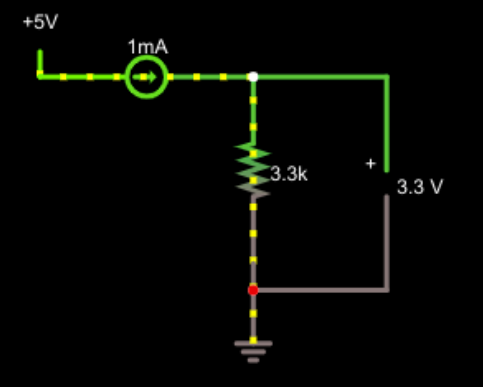 Let’s look at the normal case first.
This is pretty simple. 3.3 / 0.001 = 3,300 and that’s the answer. But real life is a little more complicated. After all, in the simulation everything is perfect, but in reality, wires are not perfect and neither are measuring devices.
Suppose the leads going to the resistor are fairly long. In fact, let’s say they add an ohm of resistance on each leg. So now instead of 3.3 kΩ you have 3.302 kΩ. That’s hardly any difference — about 0.06%. Note that measuring the voltage at the output now gives the correct result for the entire resistance, not just the resistance we are interested in.
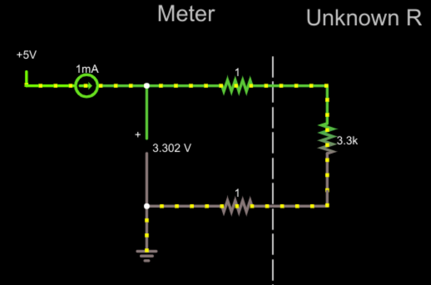
That doesn’t seem like a big deal, right? But it could be. Imagine if the unknown resistor was very small. Even, say, 1 Ω. Now we are off by a large factor! A conventional analog meter makes you zero out the probe resistance by shorting out the probes. But that requires some complexity if you are trying to get the right result to display digitally. In other words, with the perfect setup, you could put a digital panel meter that reads the voltage in the circuit, and read the resistance directly. Zeroing it out would require more effort to get the meter to read zero volts instead of the 0.002 V it would currently read with a short circuit.
Real Life
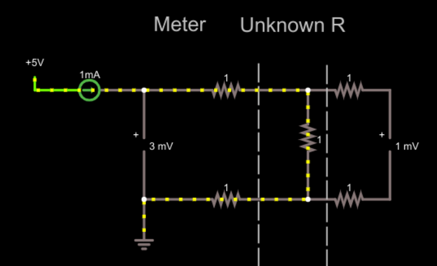 Let’s add a second voltmeter. Since the wires going to the voltmeter are perfect, we’ll also add our 1 Ω resistance to those wires. The voltmeters are perfect, too. In real life they might have a shunt resistance of a megaohm or more. You’ll see in a minute that doesn’t matter very much. But the imperfect wires do have an impact. For now, we’ll live with the perfect voltmeters.
Now the right-hand voltmeter reads correctly, despite the extra resistors. These resistors don’t matter much because the voltmeter is essentially an open circuit. No current flows so, therefore, there’s no voltage drop across the leads. In reality, there’s probably a resistance of 1 megaohm or even more across the voltmeter, but that doesn’t really make any significant difference. The reading drops to .999997 mV. Modern devices probably have at least 10 times that resistance which makes the difference truly negligible.
This is the basis of the four-wire, or Kelvin measurement. Two wires push current through the device under test and two more wires measure the voltage while transporting as little current as possible. The result is a highly accurate resistance reading.
You often hear the current carrying wires referred to as the force wires and the other pair as the sense wires. Typically the sense wires are placed between the two force wires to prevent any additional wire or trace resistance from influencing the measurement. When dealing with small measurements, it isn’t unusual to see the force wires much thicker than the sense wires. After all, the sense wires will carry very little current, but with a 0.01 Ω resistor under test the force wires will have quite a bit of current flowing.
Not just for Resistance
To recap, we wanted to measure a voltage, but were stymied by the voltage drop across the finite resistance of our current-carrying sense wires. Reducing the voltage drop, without resorting to jumper cables, means reducing the current flowing where we’re taking measurements, and the solution is to split into force wires and sense wires. Understanding the relationships intuitively about how changing one thing affects another can help you produce better designs.
This four-wire trick is useful even if you don’t want to measure resistance with precision. For example, high-current or high-accuracy regulated power supplies use the same trick. If your power supply measures voltage at the output terminals, it suffers from the same issues. Sure, you regulate to 5V at the output terminals. But a 1 Ω connector to the load drawing 2A means only 3V gets to the load!
The answer is the same. All regulated power supplies have some version of feedback coming in from the output. A remote sensing power supply will have a pair of small sense wires that connect directly to the load. Just like in the previous case, the sense wires carry very little current so they don’t suffer from as much measurement error. The voltage at the output terminals may be higher than you set the regulator, but the output across the load should be correct.
Many commercial meters — especially the bench type — offer a four-wire measurement option. Now you know how it works and why you’d use it.
No comments:
Post a Comment