Tuesday, July 31
Facebook takes on “inauthentic” meddlers ahead of major DC protest next week
Facebook took the unusual step of announcing an ongoing, incomplete investigation into "inauthentic" behavior on Tuesday, complete with implications that Russia's Internet Research Agency (IRA) may have been involved. This week's disclosure comes in part due to Facebook having to reveal its hand a bit prematurely: "32 Pages and accounts" were affiliated with a protest event scheduled for next week in Washington, DC, and Facebook has begun informing its potential attendees.
The 3,000+ users who expressed interest in the "No Unite The Right 2" event between August 10-12 in Washington, DC, will receive the following Facebook message today: "A Page created by fake accounts started the event 'No Unite The Right 2 - DC.' The other event hosts have been notified."

Read 7 remaining paragraphs | Comments


Need A Tiny CRT? Karaoke Might Just Help
[Brett] is working on a video installation, and for the past few months, has been trying to get his hands on tiny CRTs any way he can. After initially coming up short, he happened across a karaoke machine from 2005, and got down to work.
Karaoke machines of this vintage are typically fairly low-rent affairs, built cheaply on simple PCBs. [Brett] found that the unit in question was easy to disassemble, having various modules on separate PCBs joined together with ribbon cables and headers. However, such machines rarely have video inputs, as they’re really only designed to display low-res graphics from CD-G format discs.
While investigating the machine, initial research online proved fruitless. In the end, a close look at the board revealed just what [Brett] was looking for – a pin labeled video in! After throwing in a Raspberry Pi Zero and soldering up the composite output to the karaoke machine’s input pin, the screen sprung to life first time! This initial success was followed by installing a Raspberry Pi 3 for more grunt, combined with a Screenly install – and a TRS adapter the likes of which we’ve never seen before. This allows video to be easily pushed to the device remotely over WiFi. [Brett] promises us there is more to come.
Karaoke is a sparse topic in the Hackaday archives, but we’ve seen a couple builds, like this vocal processor. If you’ve got the hacks, though? You know where to send ’em.
Toyota’s heavy-duty fuel cell truck project moves from alpha to beta

In 2017, we took a look at Project Portal, Toyota's plan to test a heavy-duty, zero-emissions truck at the Ports of Long Beach and Los Angeles in California. The idea was to power an 80,000lb (36,288kg) Class-8 tractor-trailer with hydrogen fuel cells and then put it to work hauling shipping containers at one of the nation's busiest ports. Now, Toyota has taken the lessons it has learned from 10,000 miles of hard work as a drayage truck and built a second-generation vehicle with even more range.
The first truck, known as Alpha, used a pair of development powertrains from the Mirai sedan running in series. These gave it 670hp (500kW), 1,325ft-lbs (1,796Nm), and a range of 200 miles (321km). Even though Toyota has not increased the capacity of the 12kWh lithium-ion batteries on the new Beta truck, it has managed to boost that range by 50 percent to more than 300 miles (482km) between refueling. Beta retains the same power and torque output as its predecessor.
Read 3 remaining paragraphs | Comments


Dealmaster: Get a pair of Apple AirPods for $145, a rare discount
Greetings, Arsians! Courtesy of our friends at TechBargains, we have another round of deals to share. Today's list is headlined by a rare deal on Apple's popular AirPods, which are down to $145 at Amazon. That's not the lowest price we've ever seen on the little wireless earbuds, but discounts on these things aren't exactly common, so it's a solid price nonetheless.
You probably know the deal with AirPods by now. They're far from perfect: they neither feel nor sound much better than the plastic earbuds that come for free with every iPhone, they don't block outside noise well, and they only last about 4-5 hours on their own before needing to go in their charging case. But they're more than the sum of their parts. They pair easily with an iPhone, they're lightweight, and that case extends battery life by another 20+ hours. The convenience of simply popping them in and having music start playing is hard to explain until you use them.
Now, there's a big caveat here: Apple is likely to introduce new AirPods in the coming weeks. Images of an apparent charging case were discovered just this week, and past reports have suggested a pricier noise-cancelling model may also arrive down the road. But the release of new models always means discounts on the old one—if you'd rather save $14 and risk losing the better water resistance, wireless charging, and hands-free Siri expected to arrive this fall, here you go.
Read 6 remaining paragraphs | Comments


Retrotechtacular: Apex Radio — The Forgotten HiFi
Broadcasting has changed a lot in the last few decades. We have satellite radio, internet streaming, HD radio all crowding out the traditional AM and FM bands. FM became popular because the wider channels and the modulation scheme allowed for less static and better sound reproduction. If you’ve never tried to listen to an AM radio station at night near a thunderstorm, you can’t appreciate how important that is. But did you know there was another U.S. broadcast band before FM that tried to solve the AM radio problem? You don’t hear about it much, but Apex or skyscraper radio appeared between 1937 and 1941 and then vanished with the onslaught of FM radio.
If you’ve heard of Apex radio — or if you are old enough to remember it — then you are probably done with this post. For everyone else, consider what radio looked like in 1936. The AM band had 96 channels between 550 and 1500 kHz. Because those frequencies propagate long distances at night, the FCC had a complex job of ensuring stations didn’t interfere with each other. Tricks like carefully choosing the location of stations, reducing power at night, or even shutting a station down after dark, were all used to control interference.
 In addition, AM radios (like the 1924 Atwater Kent here) didn’t sound all that great. The narrow bandwidth wasn’t very enough for music reproduction. The amplitude modulation was susceptible to noise and fading. Adjacent channels had a tendency to interfere with each other. When radio appeared, it was so close to a miracle to hear anything at all that none of this seemed very important, but as it became an integral part of society, these things were all negatives.
In 1932, the FCC created three experimental frequencies at 1530, 1550, and 1570 kHz allowing a wider signal than on conventional frequencies. However, only four stations operated on these channels.
Engineering
Meanwhile, engineers were finding ways to get higher and higher frequencies. They found that above 20 MHz, propagation was usually very limited — practically line of sight in most cases. While you would think that distance is what you want in a communication system, from the FCC’s point of view being able to limit a broadcaster to the immediate area was quite attractive.
The FCC started encouraging broadcasters to experiment with “ultra high frequencies” above 20 MHz and in 1934, W8XH (a broadcaster; not a ham station) started regular broadcasts in Buffalo, New York. Part of WBEN, a traditional AM station, anyone who wanted to listen had to build their own equipment and most programming was just a rebroadcast of the companion AM station. However, in 1936 W9XAZ in Milwaukee did produce regular original programming.
 The receiver problem was particularly an issue since most receivers topped out at 20 MHz. You could build a converter, but you lost some of the advantages that way. It would be 1937 before you could buy radios like the Raco R-S-R Clipper (left), the RCA Magic Brain (see below for an example advertisement), or a McMurdo Silver (see the video, below) that could tune into the “ultra shortwave” bands. Their performance at these frequencies often left something to be desired.

As any ham will tell you, while propagation above 20 MHz is generally line of sight, it isn’t always. The FCC noted that W6XKG in Los Angles had been heard in Asia and Europe. W9XAZ would sometimes be audible in Australia along with other stations from the United States.
Apex Band
In 1937, the FCC decided to make official the high-frequency broadcast band by putting 75 channels at 41.02 MHz with 40 kHz spacing between channels. This was four times the width of an AM channel, so there was less interference and it could accommodate a better-sounding — but still AM — signal. There were about 50 stations using high frequencies that had to move to the new band. In other words, Apex was AM radio on higher frequencies with a regimented bandplan. Not bad idea at all.
 But the new band only lasted about four years. Edwin Armstrong was pushing for FM radio service, and the FCC was amazed at the audio quality possible with that system. By 1939, the commission encouraged Apex broadcasters to move to FM. In 1940, they reallocated the band to support 40 FM channels ranging from 42 to 50 MHz. RCA would later lobby to move the band again although there is a debate if it was for technical reasons or just to spite Armstrong by making his equipment obsolete.
The End
The last two Apex stations were Cleaveland’s WBOE that converted to FM in February 1941. Ironically, in 1938, it had become the first station to broadcast in the Apex channels reserved for non-commercial educational stations and Kentucky’s WBKY which closed down in June of that year.
Why the name? The line of sight broadcasting required the antenna to be up at an apex or skyscraper.
13 Useful, Cheap Product Substitutions
 Save yourself some money and time using these homemade substitutions for common arts, crafts, and maker supplies.
The post 13 Useful, Cheap Product Substitutions appeared first on Make: DIY Projects and Ideas for Makers.
Are Patent Claims Coming for Your WS2182?
There are some components which are used within our sphere so often as to become ubiquitous, referred to by their part number without the need for a hasty dig through a data sheet to remind oneself just what we are talking about. You can rattle a few of them off, the 555, the 741, the ESP8266, and so on.
In the world of LEDs, the part that most immediately springs to mind is the Worldsemi WS2812 addressable LED. This part consists of three LEDs in red, green, and blue, all in the same package with a serial interface allowing a chain of individually addressable multicolour lights to be created. We’ve seen them in all sorts of places, and if you don’t recognise the part number then perhaps you will by one of the names they’re sold under: Neopixel.
Yesterday we received an email from our piratical friends at Pimoroni, the British supplier of all forms of electronic goodies. Among their range they have a reasonable number of products containing WS2812s, and it was these products that had formed the subject of an unexpected cease-and-desist letter. APA Electronic are the manufacturer of the APA102 addressable LED (which you may know as the Dotstar), and their cease-and-desist asking for the products to be withdrawn from sale rests on their holding a patent for an addressable multicolour LED. We’d be very interested to hear whether any other suppliers of WS2812-based parts have received similar communications.

US patent number 8094102B2 is indeed a patent for a “Single full-color LED with driving mechanism”, which does look a lot like a WS2812. But as always, such things are not as cut-and-dried as they might first appear. The LED in the patent for example relies upon a clock line for its operation, while the Worldsemi part doesn’t. I am not a lawyers so I’d hesitate to call this a baseless and speculative move, but I suspect that there will be plenty over which the two semiconductor companies can duke it out in the courtroom.
It’s fair to say that a large part of the ethos of our movement shares something with that of the world of open-source, so news of legal manoeuvres such as this are never likely to go down well. We’re small fry in this context and our commercial influence on APA102 or WS2812 sales will be minimal, but inevitably APA’s standing in our eyes will be diminished. Companies such as Pimoroni are not the target but a piece of collateral damage in a battle between manufacturers.
Whether the patent has been violated or not can only be decided by the courts. It is not uncommon for patent holders to go after companies selling the “infringing” products in hopes that rather than risk a costly court battle, they simply adhere to the demands, in this case buying parts from APA and not from Worldsemi.
So, if you rely on addressable LEDs, watch out! There may be trouble ahead.
Header image: Tristan Robitaille [CC BY-SA 4.0].
The Precise Science Of Whacking A Wine Glass
It’s common knowledge that tapping a wine glass produces a pitch which can be altered by adjusting the level of the tipple of choice inside. By filling twelve glasses with different amounts of liquid and tuning them to the twelve notes of the scale, it’s possible to make a one-octave instrument – though the speed and polyphony are bottle-necked by the human operator. If you think it sounds like a ripe project for automation, you’re correct: [Bitluni’s lab] has done what needed to be done, and created a MIDI instrument which plays the glasses using mallets.
Electronically it’s a simple build – some 12 V solenoids driven by MOSFETs, with an Arduino in charge. For the mechanical build, a 3D printer proved very useful, as each mallet could be made identical, ensuring a consistent tone across all glasses. Rubber covers printed in flexible filament were fitted to reduce the overtones and produce a clearer sound. [Bitluni] also utilised different types of glasses for the low and high pitches, which also helped to improve the clarity of the tone.
MIDI is of course the perfect protocol for this application; simple, lightweight and incredibly widely used, it’s the hacker’s delight for projects like this. The instrument can perform pre-programmed sequences, or be played live with a MIDI controller. Both of these are shown in the video after the break – stick around for a unique rendition of Flight Of The Bumblebee. For a more compact wine glass based music creation solution, we recommend this nifty project, which alters pitch using a water balloon raised and lowered into the glass by a servo.
Mozilla is “evolving” the Firefox brand, and it wants your feedback
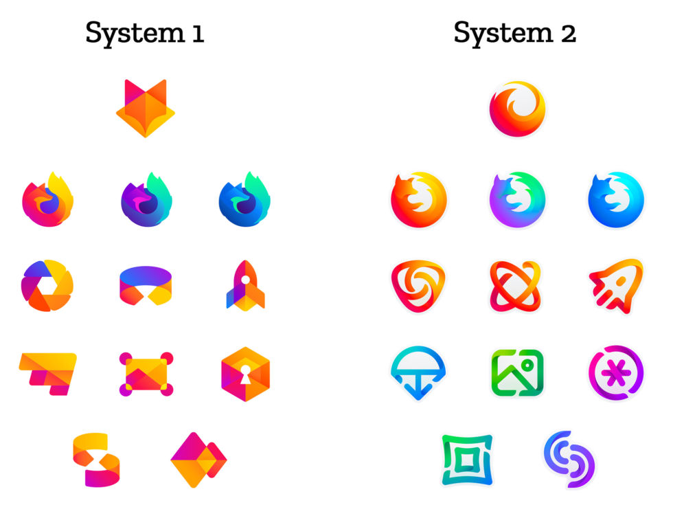
Fresh off the "Moz://a" branding from last year, Mozilla is creating new iconography for Firefox and the many Firefox derivatives it ships. The Mozilla blog showed off two competing design systems that will dictate the future look of the Firefox logo and is asking for feedback on the new designs.
The blog explains the reasoning for a redesign, saying, "As an icon, that fast fox with a flaming tail doesn’t offer enough design tools to represent this entire product family. Recoloring that logo or dissecting the fox could only take us so far. We needed to start from a new place." It produced two designs called just "System 1" and "System 2," and while there won't be any direct voting, you can leave a comment on the Mozilla blog with your preferences. Mozilla also notes these aren't final, and "Each individual icon will undergo several rounds of refinement, or may change entirely, between now and their respective product launches."
Read 2 remaining paragraphs | Comments


The Obtainium Cup Rally Is An Inspiring Excuse For Municipal Silliness
 It’s not a race, mind you, it’s a Contraptor's Rally
The post The Obtainium Cup Rally Is An Inspiring Excuse For Municipal Silliness appeared first on Make: DIY Projects and Ideas for Makers.
Best of Hangzhou Mini Maker Faire 2018
Luckily the Typhoon Ampil did not bring a lot of storms to Hangzhou city.
The post Best of Hangzhou Mini Maker Faire 2018 appeared first on Make: DIY Projects and Ideas for Makers.
Sitrep: The Air Force’s senior citizen chopper may have to hold off retirement
The US Air Force has some of the most high-tech aircraft in the world flying missions at the spear's tip. But a remarkably large number of its systems are what would gently be referred to as "vintage"—and those systems are performing some of the Air Force's most important missions. One of those senior-citizen system earned its wings during the war in Vietnam—the 48-year old UH-1 Iroquois, also known as the "Huey".
We've reported frequently on the role that the A-10 Thunderbolt II fills for the Air Force. The 1970s-era turbofan-powered tank-killer turned close-air-support-provider-extraordinaire is constantly called upon in Afghanistan and Syria to provide firepower to protect US and allied forces. The B-52, the strategic bomber that entered service in the 1950s, has years of service still ahead of it—flying long-duration missions ranging from strategic deterrence to close air support in uncontested skies. And the land leg of the US nuclear triad, the Minuteman III ICBM, entered service in the 1960s.
Read 8 remaining paragraphs | Comments


Add-On Board Brings Xbox 360 Controllers to N64
Many of the games released on the Nintendo 64 have aged remarkably well, in fact a number of them are still considered must-play experiences to this day. But the years have not been so kind to the system’s signature controller. While the N64 arguably defined the console first person shooter (FPS) genre with games like “Goldeneye” and “Perfect Dark”, a modern gamer trying to play these classics with the preposterous combination of analog and digital inputs offered by the N64 controller is unlikely to get very far.
 Of course, you could play N64 games in an emulator and use whatever controller you wish. But where’s the challenge in taking the easy way out? [Ryzee119] would much rather take the insanely complex route, and has recently completed work on an add-on board that let’s you use Xbox 360 wireless controllers on Nintendo’s 1996 console. He’s currently prepping schematics and firmware for public release, with the hope that support for additional USB controllers can be added by the community.
Nintendo historians may recall that the N64’s controllers had an expansion port on the bottom where you would connect such accessories as the “Rumble Pak” and “Controller Pak”. The former being an optional force feedback device, and the latter a rather oddly named memory card for early N64 games which didn’t feature cartridge saves. Only “90’s Kids” will recall the struggle of using the “Rumble Pak” when a game required the “Controller Pak” to save progress.
Thankfully [Ryzee119] has solved that problem by adding battery backed storage to his adapter along with some clever code which emulates the “Controller Pak”. Similarly, the “Rumble Pak” is emulated by the Xbox 360 controller’s built-in force feedback and a bit of software trickery. Specific button combinations allow for enabling and disabling the various virtual accessories on the fly.
But the best part of this modification might be how unobtrusive the whole thing is. Not only does it allow you to still use the original controllers and accessories if you wish, but it only requires soldering a handful of wires to the console’s motherboard. Thanks to the surprising amount of dead space inside the system’s case, it’s not even a challenge to fit the board inside. You do need to use the official USB Xbox 360 controller receiver, but even here [Ryzee119] opted to put a USB port on the board so you could just plug the thing in rather than having to cut the connector off and trying to solder it to the board yourself.
It probably won’t come as a surprise that this isn’t the first time [Ryzee119] has fiddled with the internals of a classic Nintendo system. We’ve previously covered his fantastic custom PCB to fit a Raspberry Pi Zero into a GameBoy Advance.
[Thanks to Gartral for the tip.]
Building the Terminator’s Arm
The Cyberdyne Systems Series 800 Terminator is a highly capable robot that happens to look an awful lot like Arnold Schwarzenegger. It boasts an advanced metallic endoskeleton, which has been the inspiration for many DIY prop builds over the years. [KenToonz] has decided to take on just such a project and invites viewers along for the ride. (YouTube, embedded below.)
The project is a particularly interesting one, as it involves the recreation of a robotic imitation of a human hand and arm. Thankfully, due to the hard work of dedicated individuals, blueprints of the original movie item are available online. These aren’t fully functional, per se, but give the aspiring builder a strong basis to get the look and feel right, while leaving room for modifications for those who wish to build something that moves and operates in the expected way. [KenToonz] intends to do exactly that, and contemplates the installation of various springs and other mechanisms to enable the joints to extend and retract properly.
[KenToonz] starts from the fingers, working back towards the forearm before beginning to add the various interstitial pieces that make it all work together as an assembly. The machining involved covers everything from small metal pieces of the digits to producing custom springs for the moving parts. We can’t wait to see the finished product once it’s all finished!
We’ve seen some great prop builds before, too – like this tricorder worthy of Mr Spock.
A Crystal Oscillator For A Stable Bench Reference
[Paul] likes a precise oscillator. His recent video shows a crystal oscillator with a “watch crystal” and a CMOS counter, the CD4060. Using such a circuit can produce very stable frequencies and since the 32.768 kHz crystal is a power of 2, you get nice divisions out of the counter.
We’ve seen the same trick done with decade counters (like the 4518B) to divide by 10 instead of powers of two to make frequency standards. A 1 MHz crystal can easily generate 100 kHz, 10 kHz, etc.
[Paul] mentions the clock is a Schmitt trigger input (he said output, but he meant input) and so it can take a noisy input from an oscillator with no problem.
The board is commercial, but the circuit is simple enough. The 4000-series CMOS is nice because you can use it over a wide voltage range and you can bias it in a linear range for things like simple crystal oscillators. Just be aware that if you do want to use a CMOS gate as a linear device you want to look for unbuffered versions (UB suffix). In 1972 the 4000A series ICs appeared and were all unbuffered. However, there were a number of flaws. The “B” series fixed some of these flaws at the expense of increasing propagation delay. by buffering. Since some designs rely on the unbuffered behavior, certain parts remain unbuffered and have a “UB” suffix.
If you want a refresher on Schmitt triggers, we have that. If you are wondering why these are called watch crystals, we can show you that, too.
Light Painting Animations Directly From Blender
Light painting: there’s something that never gets old about waving lights around in a long exposure photo. Whilst most light paintings are single shots, some artists painstakingly create frame-by-frame animations. This is pretty hard to do when moving a light around by hand: it’s mostly guesswork, as it’s difficult to see the results of your efforts until after the photo has been taken. But what if you could make the patterns really precise? What if you could model them in 3D?
[Josh Sheldon] has done just that, by creating a process which allows animations formed in Blender to be traced out in 3D as light paintings. An animation is created in Blender then each frame is automatically exported and traced out by an RGB LED on a 3D gantry. This project is the culmination of a lot of software, electronic and mechanical work, all coming together under tight tolerances, and [Josh]’s skill really shines.
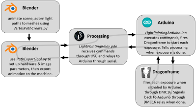
The first step was to export the animations out of Blender. Thanks to its open source nature, Python Blender add-ons were written to create light paths and convert them into an efficient sequence that could be executed by the hardware. To accommodate smooth sliding camera movements during the animation, a motion controller add-on was also written.
The gantry which carried the main LED was hand-made. We’d have been tempted to buy a 3D printer and hack it for this purpose, but [Josh] did a fantastic job on the mechanical build, gaining a solidly constructed gantry with a large range. The driver electronics were also slickly executed, with custom rack-mount units created to integrate with the DragonFrame controller used for the animation.
The video ends on a call to action: due to moving out, [Josh] was unable to continue the project but has done much of the necessary legwork. We’d love to see this project continued, and it has been documented for anyone who wishes to do so. If you want to check out more of [Josh]’s work, we’ve previously written about that time he made an automatic hole puncher for music box spools.
Thanks for the tip, [Nick].
Monday, July 30
YouTube picks up dark mode on Android, loses black bars on the Web
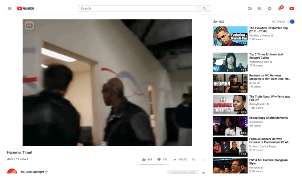
The YouTube desktop site was designed for 16:9 video, with everything in any other aspect ratio—most commonly 4:3 for old TV material or 9:16 for vertical smartphone video—padded with black bars until it fits the 16:9 box. In a change that Google is currently rolling out, those black bars are now being scrapped, and the video box will instead take on the aspect ratio of the content it's showing.
For 4:3 content, this means a bigger picture. It will be both wider and taller, pushing the title, description, and comments further down the page. For vertical video, the benefits are less apparent—empty space will open up on each side of the video—but even there, removal of the black bars means that narrow browser windows are less likely to cause the video to be sized down. Even 16:9 video is getting a little larger, with reduced margins and white space.
Read 2 remaining paragraphs | Comments


Incredible 3D Printed Overwatch Airsoft Pistol
If you ever needed evidence that gamers are some of the most dedicated individuals in all of fandom, then look no further than this fantastic 3D printed recreation of the “Pulse Pistol” as featured in the immensely popular “Overwatch”. Built by the guys at [Danger Doc], this replica doesn’t just look the part, it’s also a fully functional Airsoft gun. In the detailed build video after the break, the year-long design and construction of the gun is broken down for your viewing pleasure.
 Because the end goal was to make something that looked as though it came from the game itself, a lot of time was put into making sure that the externals were faithful to the digital version while still able to contain all the hardware they needed to cram in there. This is a fully auto gun, so it needed a battery and motors, as well as a way to feed the firing mechanism Airsoft BBs that didn’t require an anachronistic magazine sticking out.
They combined a off-the-shelf firing mechanism and high-capacity magazine but it took plenty of custom designed parts to get everything mated up. The magazine has a clockwork mechanism to advance the BBs which required the user to manually crank up, but this was replaced with an electric motor to make things a little more futuristic. In addition to all the LEDs on the body of the gun, there’s also an internal array of ultraviolet SMD LEDs to charge the glow-in-the-dark “tracer” BBs as they move through the magazine. In low light, this gives the shots from the gun something of a laser effect.
We’ve seen 3D printed guns from games before, but rarely with this attention to detail and engineering. Honestly, this even gives some real 3D printed guns a run for their money.
Google and Facebook, sure, but CNN’s The 2000s puts Microsoft vs. Apple centerstage
The promo for The 2000s.
"We're in for the communications ride of our lives," CNN's Greg Lefevre says in a January 2, 2000, broadcast dug up for the news network's latest decade documentary, The 2000s. "The coming years see cell phones small enough to fit in your pocket, the promise of video phones coming true, tiny hand sized computers that know your favorite subjects, and Internet everywhere."
Talk about prescience. Though most people reading this website can likely remember the 2000s as if it were yesterday, retrospectives and nostalgia have started to come in. And even if it feels a bit too soon-ish for such treatment, it's hard to argue with the need to acknowledge the time period's relevance and impact. The previous decade unequivocally changed the way we operate in a technological sense: the rise of smartphones, the start of companies like Facebook, Google, and YouTube, the ability to get whatever you want whenever you want it.
CNN has been producing these decade projects for a while now—its hour on tech in the 1990s ended up among our favorite hours of 2017 TV—and it would be easy for last night's installment to feel particularly unsurprising. After all, "The iDecade" episode of The 2000s sets out to detail the evolution of technology from 2000 through 2010, essentially spelling out how today became today.
Read 6 remaining paragraphs | Comments


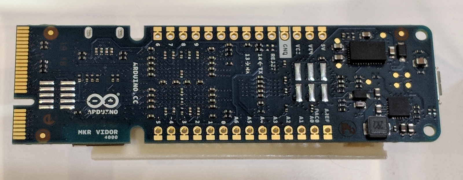
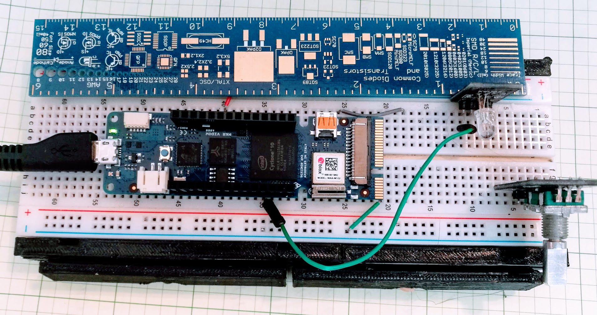
Hands-On with New Arduino FPGA Board: MKR Vidor 4000
Hackaday brought you a first look the Arduino MKR Vidor 4000 when it announced. Arduino sent over one of the first boards so now we finally have our hands on one! It’s early and the documentation is still a bit sparse, but we did get it up and running to take the board through some hello world exercises. This article will go over what we’ve been able to figure out about the FPGA system so far to help get you up and running with the new hardware.
Just to refresh your memory, here’s what is on the Vidor board:
- 8 MB SRAM
- A 2 MB QSPI Flash chip — 1 MB allocated for user applications
- A Micro HDMI connector
- An MIPI camera connector
- Wi-Fi and BLE powered by a U-BLOX NINA W10 Series device
- MKR interface on which all pins are driven both by SAMD21 (32-bit ARM CPU) and FPGA
- Mini PCI Express connector with up to 25 user programmable pins
- The FPGA (an Intel/Altera Cyclone 10CL016) contains 16K Logic Elements, 504 KB of embedded RAM, and 56 18×18 bit HW multipliers
Sounds good. You can get more gory technical details over at Arduino and there’s even a schematic (.zip).
Documentation
Documentation is — so far — very hard to come by but the team is working to change that by the day. Here are the resources we’ve used so far (in addition to the schematic):
- A getting started guide
- A GitHub site with three repositories: An example for general I/O in the FPGA, an example for video, and a stripped down example that loads an unknown — possibly default — bitstream
- A very generic document about FPGA coding
- The forum for the MKR 4000
In addition, Arduino just released an example FPGA project for Quartus. I’ll explain what that means in a bit.
Get Up and Running with the Arduino Desktop IDE
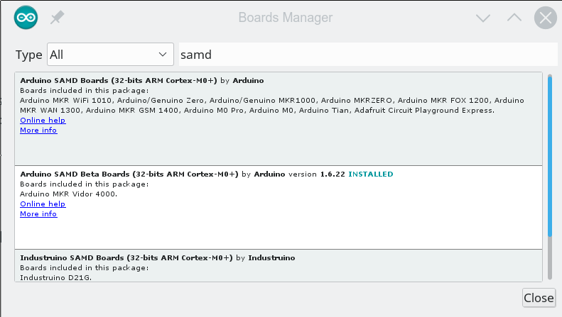
Despite the getting started guide, it doesn’t appear the libraries are usable from the cloud-based IDE, so we followed the instructions to load the beta board support for the MKR 4000 into our desktop IDE. Be aware that the instructions show the “normal” SAMD board package, but you actually want the beta which says it is for the MKR 4000. If you search for SAMD in the Boards Manager dialog, you’ll find it (see the second entry in the image below).
The libraries we grabbed as ZIP files from GitHub and used the install library from ZIP file option with no problems.
What’s the Code Look Like?
The most interesting part of this board is of course the inclusion of the FPGA which left us wondering what the code for the device would look like. Browsing the code, we were a bit dismayed at the lack of comments in all but the JTAG code. We decided to focus first on the VidorPeripherals repository and dug into the header file for some clues on how everything works.
Looking at VidorPeripherals.h, you can see that there’s a few interesting I/O devices include SPI, I2C, UART, reading a quadrature encoder, and NeoPixel. There’s also a few headers that don’t exist (and presumably won’t get the define to turn them on) so don’t get too excited by some of the header file names until you make sure they are really there.
Then we decided to try the example test code. The library provides a global FPGA object that you need to set up:
// Let's start by initializing the FPGA
if (!FPGA.begin()) {
    Serial.println("Initialization failed!");
    while (1) {}
}

// Let's discover which version we are running
int version = FPGA.version();
Serial.print("Vidor bitstream version: ");
Serial.println(version, HEX);

// Let's also ask which IPs are included in this bitstream
FPGA.printConfig();
The output of this bit of code looks like this:
Vidor bitstream version: 1020107
number of devices 9
1 01000000 MB_DEV_SF
1 02000000 MB_DEV_GPIO
4 04000000 MB_DEV_I2C
6 05000000 MB_DEV_SPI
8 06000000 MB_DEV_UART
1 08000000 MB_DEV_SDRAM
4 09000000 MB_DEV_NP
11 0A000000 MB_DEV_ENC
0 0B000000 MB_DEV_REG
In many cases, the devices provided by the FPGA are pretty transparent. For example, here’s another snip from the example code:
// Ok, so we know now that the FPGA contains the extended GPIO IP
// The GPIO pins controlled by the FPGA start from 100
// Please refer to the online documentation for the actual pin assignment
// Let's configure pin A0 to be an output, controlled by the FPGA
FPGA.pinMode(33, OUTPUT);
FPGA.digitalWrite(33, HIGH);

// The same pin can be read by the SAMD processor :)
pinMode(A0, INPUT);
Serial.print("Pin A0 is ");
Serial.println(digitalRead(A0) == LOW ? "LOW" : "HIGH");

FPGA.digitalWrite(33, LOW);
Serial.print("Pin A0 is ");
Serial.println(digitalRead(A0) == LOW ? "LOW" : "HIGH");
That’s easy enough and it is nice that the pins are usable from the CPU and FPGA. We couldn’t find the documentation mapping the pins, but we assume it is coming.
Using, say, an extra serial interface is easy, too:
SerialFPGA1.begin(115200);
while (!SerialFPGA1);
SerialFPGA1.println("test");
Bitstream
So where’s the FPGA code? As far as you can tell, this is just a new Arduino with a lot of extra devices that connect through this mysterious FPGA object. The trick is that the FPGA code is in the library. To see how it works, let’s talk a little about how an FPGA operates.
When you write a program in C, that’s not really what the computer looks at, right? The compiler converts it into a bunch of numbers that tell the CPU to do things. An FPGA is both the same and different from that. You write your program — usually in a hardware design language like Verilog or VHDL. You compile it to numbers, but those numbers don’t get executed like a CPU does.
The best analogy I’ve been able to think of is that an FPGA is like one of those old Radio Shack 100-in-1 electronic kits. There are a bunch of parts on a board and some way to connect them with wires. Put the wires one way and you have a radio. Put them another way and you have a burglar alarm. Rewire it again and you have a metal detector. The numbers correspond to wires. They make connections and configure options in the FPGA’s circuitry. Unless you’ve built a CPU, there’s nothing in there examining and acting on the numbers like there would be with a CPU.
The numbers that come out of an FPGA tool is usually called a bitstream. Someone has to send that bitstream to an FPGA like the Cyclone onboard the Arduino every time it powers up. That someone is usually a memory device on the board, although the CPU can do it, too.
So that leads to two questions: Where is the bitstream? How does it get to the FPGA?
The answer to the first question is easy. If you look on Github, you’ll see in the library there is a file called VidorBase.cpp. It has the following lines:
__attribute__ ((used, section(".fpga_bitstream")))
const unsigned char bitstream[] = {
    #include "app.ttf"
};
What this means if there is an array called bitstream that the linker will put it in a specially marked section of memory. That array gets initialized with app.ttf which is just an ASCII file full of numbers. Despite the name, it is not a TrueType font. What do the numbers mean? Hard to say, although, in theory, you could reverse engineer it just like you can disassemble binary code for a CPU. However, it is the configuration required to make all the library calls we just talked about work.
The second question about how it gets to the FPGA configuration is a bit of a mystery. As far as we can tell, the bootloader understands that data in that section should get copied over to the FPGA configuration memory and does the copying for you. It isn’t clear if there’s a copy in the main flash and a copy in the configuration flash but it seems to work transparently in any event.
There’s a checksum defined in the code but we changed it and everything still worked. Presumably, at some point, the IDE or the bootloader will complain if you have the wrong checksum, but that doesn’t appear to be the case now.
By the way, according to the Arduino forum, there are actually two bitstreams. One that loads on power-up that you would rarely (if ever) change. Then there is another that is the one included with the library. You can double-click the reset button to enter bootloader mode and we suspect that leaves the FPGA initialized with the first bitstream, but we don’t know that for sure. In bootloader mode, though, the red LED onboard has a breathing effect so you can tell the double click works.
What about my FPGA Code?
 This isn’t great news if you were hoping for an easy Arduino-like way to do your own FPGA development in Verilog or VHDL. Intel will give you a copy of Quartus Prime which will generate bitstreams all day for you. We think — but we aren’t sure — that the ASCII format is just a raw conversion from binary of the bitstream files.
Very recently, Arduino provided a Quartus project that would create a bitstream. This provides a few key pieces of the puzzle, like the constraint file that lets the FPGA compiler find the different parts on the board.
However, even with that project, you still have some reverse engineering to do if you want to get started. Why? Here’s what Arduino says about loading your own FPGA code (we added the emphasis):
Quartus will produce a set of files under the output_files directory in the project folder. In order to incorporate the FPGA in the Arduino code you need to create a library and preprocess the ttf file generated by Quartus so that it contains the appropriate headers required by the software infrastructure. Details of this process will be disclosed as soon as the flow is stable.
Programming the FPGA is possible in various ways:
- Flashing the image along with Arduino code creating a library which incorporates the ttf file
- Programming the image in RAM through USB Blaster (this requires mounting the FPGA JTAG header). this can be done safely only when SAM D21 is in bootloader mode as in other conditions it may access JTAG and cause a contention
- Programming the image in RAM through the emulated USB Blaster via SAM D21 (this component is pending release)
In addition, the repository itself says that some key pieces are missing until they can work out licensing or clean up the code. So this gets us closer, but you’d still need to reverse engineer the header from the examples and/or figure out how to force the processor off the JTAG bus. The good news is it sounds like this information is coming, it just isn’t here yet.
Of course, you are going to need to understand a lot more to do anything significant. We know the FPGA is set in the AS configuration mode. We also asked Arduino about the clock architecture of the board and they told us:
[The CPU] has its own clock which is used to generate a 48 MHz reference clock that is fed to the FPGA (and that can be removed at any time to “freeze” fpga). In addition to this reference clock, [the] FPGA has an internal RC oscillator which can’t be used as [a] precise timing reference for tolerance issues but can be used in case you don’t want [the CPU] to produce the reference clock.
Of course, the FPGA has a number of PLLs onboard that can take any valid clock and produce other frequencies. For example, in the vision application, Arduino demonstrated, the 48 MHz clock is converted into 24 MHz, 60 MHz, 100 MHz, and 120 MHz clocks by PLLs.
Mix and Match?
 One thing that is disappointing is that — at least for now — you won’t be able to mix and match different FPGA libraries. There is exactly one bitstream and you can’t just jam them together. Although FPGAs can often be partially configured, that’s a difficult technique. But we were a little surprised that the IDE didn’t understand how to take libraries with, for example, EDIF design files for IP that would all get compiled together. That way I could pick the Arduino UART and mix it with the Hackaday PWM output module along with my own Verilog or VHDL.
The way things are structured now you will have one bitstream that is precompiled by another tool (probably Quartus for the foreseeable future). It will match up with a particular C++ library. And that’s it. Doesn’t matter how much of the FPGA is left over or how much of it you really use, you will use it all for the one library.
Of course, you can load another library but it is going to replace the first one. So you only get one set of functions at a time and someone else gets to decide what’s in that set. If you roll your own, you are going to have to roll your own all the way.
What’s Next?
It is still early for the Arduino Vidor. We are hopeful we’ll get the tools and procedures necessary to drop our own FPGA configurations in. It would be great, too, if the stock libraries were available in source format including the Verilog HDL. The recent GitHub release shows quite a bit, although it isn’t all of the examples, it is probably enough if we get the rest of the information.
As for a more intuitive interface, we don’t know if that’s in the cards or not. We don’t see much evidence of it, although posts on the Arduino forum indicate they will eventually supply an “IP Assembler” that will let you compose different modules into one bitstream. We don’t know if that will only work with “official” modules or not. However, we know the Arduino community is very resourceful so if we don’t get a good ecosystem it will not surprise us if someone else makes it happen. Eventually.
For now, we will continue to play with the existing bitstreams that become available. There are some neat new features on the CPU, too. For example, you can map two of the unused serial modules. There’s a hardware-based cooperative multitasking capability. As more details on the FPGA emerge, we’ll keep you posted and if you learn something, be sure to leave word in the comments so everyone can benefit.
Google Pixel 3 rumors: More pictures leak, hints of smart display dock surface
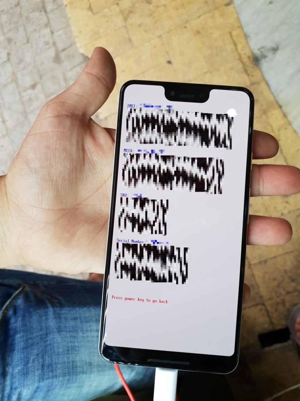
A pair of Pixel news items hit the Internet this weekend. First up, we have more leaked pictures of Google's upcoming Pixel 3 XL flagship, this time in white to go along with the previously leaked black version.
The pictures, which were taken by XDA forum user dr.guru, line up well with the previous Pixel pictures, showing a device with a very tall top notch, a bottom chin bezel, and what looks to be front-facing stereo speakers. It looks like Google is still bucking all the camera trends with two front-facing cameras and one rear camera. The post said the device was remote wiped by Google, but the bootloader shows a Snapdragon 845 device codenamed "Crosshatch," with 4GB of RAM and 64GB of storage. The previous leak was a 128GB version.
Read 4 remaining paragraphs | Comments

