When it comes to building sets and props for movies and TV, it’s so easy to get science fiction wrong – particularly with low-budget productions. It must be tempting for the set department to fall back on the “get a bunch of stuff and paint it silver” model, which can make for a tedious experience for the technically savvy in the audience.
But low-budget does not necessarily mean low production values if the right people are involved. Take [Joel Hartlaub]’s recent work building sets for a crowdfunded sci-fi film called Infinitus. It’s a post-apocalyptic story that needed an underground bunker with a Fallout vibe to it, and [Joel] jumped at the chance to hack the sets together. Using mainly vintage electronic gear and foam insulation boards CNC-routed into convincing panels, he built nicely detailed control consoles for the bunker. A voice communicator was built from an old tube-type table radio case with some seven-segment displays, and the chassis of an old LCD projector made a convincing portable computer terminal. The nicest hack was for the control panel of the airlock door. That used an old TDD, or telecommunications device for the deaf. With a keyboard and a VFD display, it fit right into the feel of the set. But [Joel] went the extra mile to make it a practical piece, by recording the modulated tones from the acoustic coupler and playing them back, to make it look as if a message was coming in. The airlock door looks great too.
Like many hacks, it’s pretty impressive what you can accomplish with a deep junk pile and a little imagination. But if you’ve got a bigger budget and you need some computer displays created, we know just the person for the job.
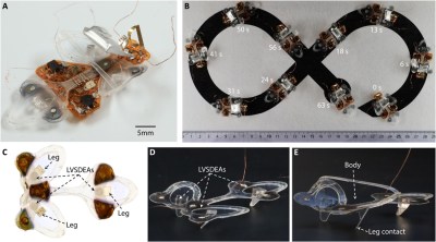
Swarms of robotic insects incapable of being swatted away may no longer be the product of science fiction and Black Mirror episodes. A team from EPFL’s School of Engineering has developed an insect propelled at 3 cm/s, dubbed the DEAnsect.
What makes this robot unique is its exceptional robustness. Two versions of the robot were initially developed, one tethered with ultra-thin wires capable of being squashed with a shoe without impacting its functions and the second fully wireless and autonomous. The robot weighs less than 1 gram and is equipped with a microcontroller and photodiodes to recognize black and white patterns.
The insect is named for its dielectric elastomer actuators (DEAs), an artificial muscle that propels it with vibrations and enables it to move lightly and quickly.
The DEAs are made of an elastomer membrane wedged between soft electrodes that are attracted to each other when a voltage is applied, compressing the membrane. The membrane returns to its original shape when the voltage is turned off. Movement is generated by switching the voltage on and off over 400 times per second. The team reduced the thickness of the membranes and developed soft, highly conductive electrodes only several molecules thick using nanofabrication techniques. They plan on fitting even more sensors and emitters to allow the insects to communicate directly with one another for greater swarm-like activity.
If you’re going to fail, you might as well fail ambitiously. A complex project with a lot of subsystems has a greater chance of at least partial success, as well as providing valuable lessons in what not to do next time. At least that’s the lemonade [Josh Johnson] made from his lemon of a lost-cost vector network analyzer.
For the uninitiated, a VNA is a versatile test instrument for RF work that allows you to measure both the amplitude and the phase of a signal, and it can be used for everything from antenna and filter design to characterizing transmission lines. [Josh] decided to port a lot of functionality for his low-cost VNA to a host computer and concentrate on the various RF stages of the design. Unfortunately, [Josh] found the performance of the completed VNA to be wanting, especially in the phase measurement department. He has a complete analysis of the failure modes in his thesis, but the short story is poor filtering of harmonics from the local oscillator, unexpected behavior by the AD8302 chip at the heart of his design, and calibration issues. Confounding these issues was the time constraint; [Josh] might well have gotten the issues sorted out had the clock not run out on the school year.
After reading through [Josh]’s description of his project, which was a final-year project and part of his thesis, we feel like his rating of the build as a failure is a bit harsh. Ambitious, perhaps, but with a spate of low-cost VNAs coming on the market, we can see where he got the inspiration. We understand [Josh]’s disappointment, but there were a lot of wins here, from the excellent build quality to the top-notch documentation.
The last ten years will arguably be seen as the "decade of the exoplanet." That might seem like an obvious thing to say, given that the discovery of the first exoplanet was honored with a Nobel Prize this year. But that discovery happened back in 1995—so what made the 2010s so pivotal?
One key event: 2009's launch of the Kepler planet-hunting probe. Kepler spawned a completely new scientific discipline, one that has moved from basic discovery—there are exoplanets!—to inferring exoplanetary composition, figuring out exoplanetary atmosphere, and pondering what exoplanets might tell us about prospects for life outside our Solar System.
To get a sense of how this happened, we talked to someone who was in the field when the decade started: Andrew Szentgyorgyi, currently at the Harvard-Smithsonian Center for Astrophysics, where he's the principal investigator on the Giant Magellan Telescope's Large Earth Finder instrument. In addition to being famous for having taught your author his "intro to physics" course, Szentgyorgyi was working on a similar instrument when the first exoplanet was discovered.
The year is 150 CE. It’s a humid summer day in Muyil, a coastal Mayan settlement nestled in a lush wetland on the Yucatan Peninsula. A salty breeze blows in from the gulf, rippling the turquoise surface of a nearby lagoon. Soon, the sky darkens. Rain churns the water, turning it dark and murky with stirred-up sediment. When the hurricane hits, it strips leaves off the mangroves lining the lagoon’s sandy banks. Beneath the tumultuous waves, some drift gently downward into the belly of the sinkhole at its center.
Nearly two millennia later, a team of paleoclimatologists have used sediment cores taken from Laguna Muyil’s sinkhole to reconstruct a 2,000-year record of hurricanes that have passed within 30 kilometers of the site. Richard Sullivan of Texas A&M presented the team's preliminary findings this month at AGU’s Fall Meeting. The reconstruction shows a clear link between warmer periods and an increased frequency of intense hurricanes.
This long-term record can help us better understand how hurricanes affected the civilization that occupied the Yucatan Peninsula for thousands of years. It also provides important information to researchers hoping to understand how hurricanes react to long-term climate trends in light of today’s changing climate.
[Bwack] had some scanned pictures of an old Commodore card and wanted to recreate PC boards from it. It’s true that he could have just manually redrawn everything in a CAD package, but that’s tedious. Instead, he used SprintLayout 6.0 which allows you to import pictures and use them as a guide for recreating a PCB layout.
You can see the entire process including straightening the original scans. There are tools that make it very easy to place new structures over the original scanned images.
One might think the process could be more automated, but it looks as though every piece needs to be touched at least once, but it is still easier than just trying to eyeball everything together.
Most of the video is sped up, which makes it look as though he’s really fast. Your speed will be less, but it is still fairly quick to go from a scan to a reasonable layout.
The software is not free, but you can do something somewhat similar in KiCAD. The trick is to get the image scaled perfectly and convert it to a component on a user layer. Then you can add the new component and enable the user layer to see the image as you work. There’s even a repository of old boards recreated in KiCAD.
By now most readers will be familiar with the Miniware TS100 and TS80 soldering irons, compact and lightweight temperature controlled soldering tools that have set a new standard at the lower-priced end of the decent soldering iron market. We know they have an STM32 processor, a USB interface, and an OLED display, and that there have been a variety of alternative firmwares produced for them.
Take a close look at the TS80, and you’ll find the element connector is rather familiar. It’s a 3.5 mm jack plug, something we’re more used to as an audio connector. Surely audio from a soldering iron would be crazy? Not if you are [Joric], who has created a music player firmware for the little USB-C iron. It’s hardly a tour de force of musical entertainment and it won’t pull away the audiophiles from their reference DACs, but it does at least produce a recognisable We Wish You A Merry Christmas as you’ll see from the video below the break.
Since the TS100 arrived a couple of years ago we’ve seen a variety of inventive firmware for it. You may remember [Joric]’s previous triumph of a Tetris game for the iron, but our favourite is probably the TS100 oscilloscope.
In any normal situation, if you’d read an article that about building your own quantum computer, a fully understandable and natural reaction would be to call it clickbaity poppycock. But an event like the Chaos Communication Congress is anything but a normal situation, and you never know who will show up and what background they will come from. A case in point: security veteran [Yann Allain] who is in fact building his own quantum computer in his garage.
Starting with an introduction to quantum computing itself, and what makes it so powerful also in the context of security, [Yann] continues to tell about his journey of building a quantum computer on his own. His goal was to build a stable computer he could “easily” create by himself in his garage, which will work at room temperature, using trapped ion technology. After a few iterations, he eventually created a prototype with KiCad that he cut into an empty ceramic chip carrier with a hobbyist CNC router, which will survive when placed in a vacuum chamber. While he is still working on a DIY laser system, he feels confident to be on the right track, and his estimate is that his prototype will achieve 10-15 qubits with a single ion trap, aiming to chain several ion traps later on.
As quantum computing is often depicted as cryptography’s doomsday device, it’s of course of concern that someone might just build one in their garage, but in order to improve future cryptographic systems, it also requires to fully understand — also on a practical level — quantum computing itself. Whether you want to replicate one yourself, at a rough cost of “below 15k Euro so far” is of course a different story, but who knows, maybe [Yann] might become the Josef Prusa of quantum computers one day.
Most of these stories start with a cat standing on someone’s chest, begging for food at some obscene hour of the morning. But not this one. Chaz the cat is diabetic, and he needs to get his insulin with breakfast. The problem is that Chaz likes to eat overnight, which ruins his breakfast appetite and his chances at properly metabolizing the insulin. [Becky] tried putting the bowl away before bed, but let’s face it — it’s more fun to solve a problem once than to solve the same problem every night.
[Becky]’s solution was to design and print a bowl holder with a lid, and to cover the bowl when the cat diner is closed using a small servo and a NodeMCU. It looks good, and it gets the job done with few components. Chaz gets his insulin, [Becky] gets peace of mind, and everybody’s happy. This isn’t going to work for all cats, because security is pretty lax. But Chaz is a senior kitty and therefore disinterested in pawing at the lid to see what happens. Claw your way past the break to see [Becky]’s build/demo video featuring plenty of cat tax coverage.
SIM cards are all around us, and with the continuing growth of the Internet of Things, spawning technologies like NB-IoT, this might as well be very literal soon. But what do we really know about them, their internal structure, and their communication protocols? And by extension, their security? To shine some light on these questions, open source and mobile device titan [LaForge] gave an introductory talk about SIM card technologies at the 36C3 in Leipzig, Germany.
Starting with a brief history lesson on the early days of cellular networks based on the German C-Netz, and the origin of the SIM card itself, [LaForge] goes through the main specification and technology parts of each following generation from 2G to 5G. Covering the physical basics, I/O interfaces, communication protocols, and the file system located on the SIM card, you’ll get the answer to “what on Earth is PIN2 for?” along the way.
Of course, a talk like this, on a CCC event, wouldn’t be complete without a deep and critical look at the security side as well. Considering how over-the-air updates on both software and — thanks to mostly running Java nowadays — feature side are more and more common, there certainly is something to look at.
A number of years back, there was a great deal of excitement about using viruses to target cancer. A number of viruses explode the cells that they've infected in order to spread to new ones. Engineering those viruses so that they could only grow in cancer cells would seem to provide a way of selectively killing these cells. And some preliminary tests were promising, showing massive tumors nearly disappearing.
But the results were inconsistent, and there were complications. The immune system would respond to the virus, limiting our ability to use it more than once. And some of the tumor killing seemed to be the result of the immune system, rather than the virus.
Now, some researchers have focused on the immune response, inducing it at the site of the tumor. And they do so by remarkably simple method: injecting the tumor with the flu vaccine. As a bonus, the mice it was tested on were successfully immunized, too.
Focus stacking is a photographic technique in which multiple exposures are taken of a subject, with the focus distance set to different lengths. These images are then composited together to create a final image with a greater depth of field than is possible with a single exposure. [Peter Lin] built a rig for accurate focus stacking with very small subjects.
The heart of the rig is a motion platform consisting of a tiny stepper motor fitted with a linear slide screw. This is connected to an Arduino or PIC with a basic stepper driver board. While the motor does not respond well to microstepping or other advanced techniques, simply driving it properly can give a resolution of 15 μm per step.
The motor/slide combination is not particularly powerful, and thus cannot readily be used to move the camera or optics. Instead, the rig is designed for photography of very small objects, in which the rail will move the subject itself.
It’s a tidy build that would serve well for anyone regularly doing macro focus stack photography. If you’ve been trying to better photograph your insect collection, this one is for you. It’s a valuable technique and one that applies to microscopy too. Video after the break.
Enlarge/ A Comcast van in Sunnyvale, California, in November 2018. (credit: Getty Images | Andrei Stanescu)
A whole slew of cable companies are notching up a victory in a lawsuit against the state of Maine that seeks to block a recent law that would require à la carte cable offerings.
Comcast spearheaded the coalition of companies, which filed the suit in September. The Maine law, the first of its kind in the nation, was invalid for two reasons, the suit argued: first, because it pre-empts federal communications law, and second, because it violates companies' First Amendment rights. Comcast was joined by more than a dozen other plaintiffs, including its own NBCUniversal subsidiary, CBS, Viacom (which had not yet completed its merger with CBS), Disney, Fox, A&A, Discovery, and Hearst.
As is common in such suits, the plaintiffs first sought an injunction that would block the state from enforcing the law while the rest of the legal process gets sorted out. District Judge Nancy Torresen granted the injunction in a ruling (PDF) issued just before Christmas.
Courtesy of the National Institute of Standards and Technology.
It has been more than 50 years since the assassination of President John F. Kennedy shocked the nation, but the case still generates considerable public interest—particularly fragments from the bullets that killed the president, which have been preserved in a temperature and humidity-controlled vault at the National Archives and Records Administration in Washington, DC, for decades. Scientists at the National Institute of Standards and Technology (NIST) recently teamed up with forensic experts at the National Archives to digitize the bullets, the better to preserve their features for the conspiracy theorists of tomorrow. All the data should be available in the National Archives' online catalog sometime in early 2020.
There are two fragments of the bullets that killed JFK—one that hit him in the neck and another that hit him in the back of the head—as well as the so-called "stretcher bullet." That's the bullet that struck the president and also Texas Governor John Connally, found lying near the latter's stretcher at the hospital. Also in the archives: two bullets used in a test firing of the assassin's rifle for forensic matching purposes.
The curators from the National Archives were on site while all the analysis was being done, locking up the precious artifacts in a safe every night to ensure their safety. The biggest challenge, according to NIST's Thomas Brian Renegar, was figuring out how to make measurements in sufficient detail to create the kind of 3D models they needed. For instance, "How do we hold the artifacts safely and securely?" he told Ars. "We don't want them moving while we're doing the scans, but we need to hold them carefully so as not to damage the artifacts." The fragments in particular are also badly warped and twisted, making surface scanning difficult.
The first thing Jeremy Cook thought when he saw a video of Theo Jansen’s Strandbeest walking across the beach was how incredible the machine looked. His second thought was that there was no way he’d ever be able to build something like that himself. It’s a feeling that most of us have had at one time or another, especially when starting down a path we’ve never been on before.
But those doubts didn’t keep him from researching how the Strandbeest worked, or stop him from taking the first tentative steps towards building his own version. It certainly didn’t happen overnight. It didn’t happen over a month or even a year, either.
His first builds could barely move, and when they did, it wasn’t for long. But the latest version, which he demonstrated live in front of a packed audience at the LA College of Music, trotted across the stage with an almost otherworldly smoothness. To say that he’s gotten good at building these machines would be something of an understatement.
Jeremy’s talk is primarily focused on his Strandbeest creations, but it’s also a fascinating look at how a person can gradually move from inspiration to mastery through incremental improvements. He could have stopped after the first, second, or even third failure. But instead he persisted to the point he’s an expert at something he once believed was out of his reach.
Learning to Crawl
There’s a well known Chinese proverb that, roughly translated, states “a journey of a thousand miles begins with a single step.” It’s something to keep in mind any time you take on a challenge, but it rings especially true for anyone looking to build a Strandbeest. Rather than trying to tackle the entire machine at once, Jeremy thought a reasonable enough approach to constructing a multi-legged walking robot was to first build a single leg and understand how it operates.
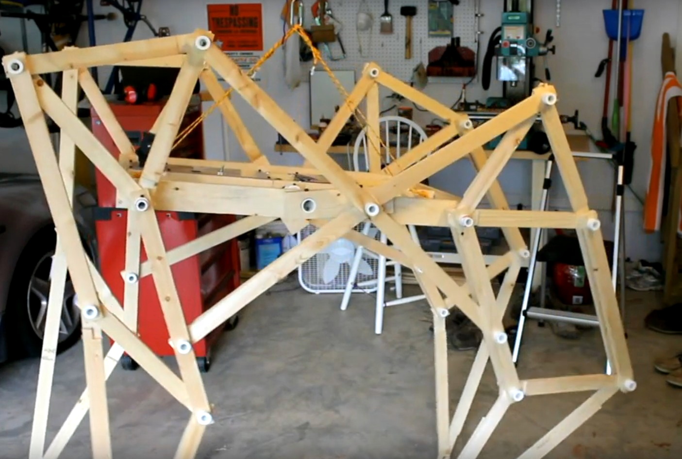
One of the early wooden designs.
With one leg built and working, the next step was of course to build more of them. When he had four assembled, it was time to design a base to mount them on, and then outfit it with electric motors to get things moving.
Unfortunately this first Strandbeest, made of wood and roughly the size of a golf cart, never worked very well. Jeremy attributes its failure to a number of issues which he would eventually learn to solve, such as imprecision in the linkages, excessive friction, and undersized motors. That first build may have failed as a walker, but it served as a fantastic learning experience.
For the second Strandbeest Jeremy switched over to cutting the parts out of MDF, but the contraption was still too heavy. This version was even less successful than the first, and it soon fell apart. It seemed clear at this point that the way forward was to scale the design down to a more manageable size.
The Next Generation
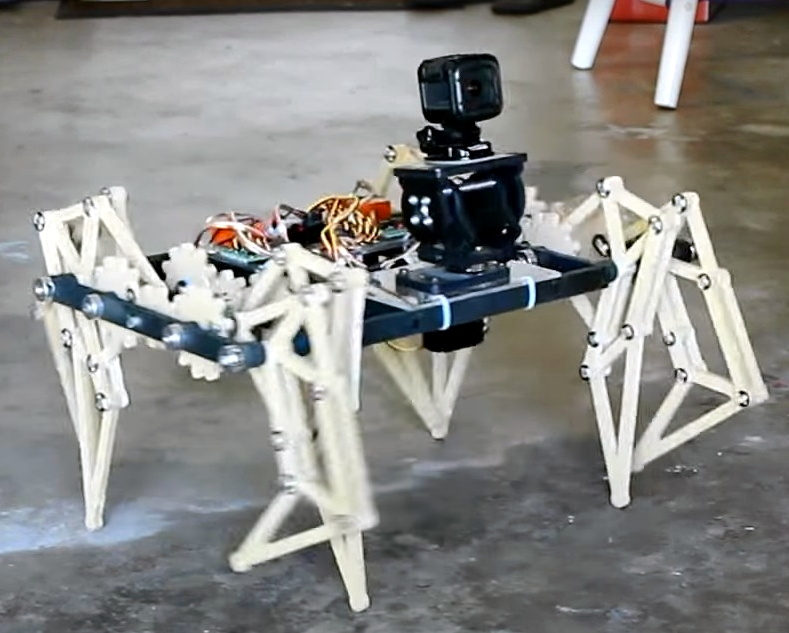
Once he shrunk the walker’s design down to tabletop scale, Jeremy really started seeing some progress. It still took a few iterations to get something that could move around without jamming up or rattling itself to pieces, but with parts that could be accurately cut on a CNC router and the addition of a new geared drive system, these smaller Strandbeests really started to come alive.
Smaller, gear-driven, walkers proved successful
Not only did they perform much better, but the eventual switch to clear acrylic gave them a very distinctive look. Around this time, Jeremy also started to add some anthropomorphic features, like articulated “heads” that housed cameras or LED “eyes”. These features not only gave his bots the ability to emote, but also marked a clear separation between his creations and that of Theo Jansen, who’s designs were only getting larger and more alien as time went on.
The latest and greatest of these acrylic Strandbeests is the ClearCrawler, which takes into account all the lessons Jeremy has learned over the years. Powered by an Arduino Nano and controllable via a custom handheld remote using nRF24L01 modules, this walker is easily expandable and provides an excellent platform for further research and exploration.
Staying Humble
Despite the leaps and bounds that Jeremy has made with his Strandbeests, he still remains in awe of the original wind-powered walkers that Theo Jansen unveiled all those years ago. If anything, he says he has more respect for those creations now than when he first saw them. Looking at it with no knowledge of how it works, you’ll of course be impressed. But once you understand the mechanisms involved, and just how hard it is to build and operate these creations, you realize what a monumental accomplishment it really was.
Which is perhaps the real lesson to be learned after watching Jeremy’s talk: there’s always more to learn and be impressed by. Even if you’ve been working on a particular project for years and now are at the point where you’re giving presentations on it at a hardware hacking conference, don’t be surprised if you still find yourself scratching your head from time to time. Rather than being discouraged, use the experience as inspiration to keep pushing forward and learning more.
Shell scripting is handy and with a shell like bash it is very capable, too. However, shell scripting isn’t always very efficient. Think about it. If you run grep or tr or sort to do some operation in a shell script, you are spawning a whole new process. That takes time and resources. But there are some answers to reducing — but not eliminating — the problem.
Have you ever written a program like this (in any language, but I’ll use C):
int foo(void)
{
  ...
  bar();

}
You hope the compiler doesn’t write assembly code like this:
_foo:
....

      call _bar
      ret
Most optimizers should pick up on the fact that you can convert a call like this to a jump and let the ret statement in _bar return to foo’s caller. However, shell scripts are not that smart. If you have a shell script called MungeData and it calls another program or shell script called PostProcess on its last line, then you will have at one time three processes in play: your original shell, the shell running MungeData, and either the PostProcess program or a shell running the script. Not to mention, the processes to do things inside post process. So what do you do?
Enter Exec
There are a few possible answers to this, but in the particular case where one shell script calls another program or script at the end, the answer is easy. Use exec:
#!/bin/bash
# Do stuff here
...
# Almost done
exec PostProcess
This tells the shell to reuse the current process for PostProcess. Nothing that appears after the exec will run because the current process is wiped out. When PostProcess completes, the original process that called our script will resume. This is pretty much the same as the call/ret to jump optimization in C.
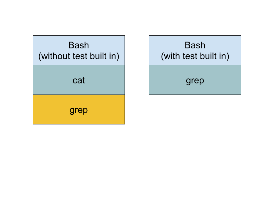
Built Ins
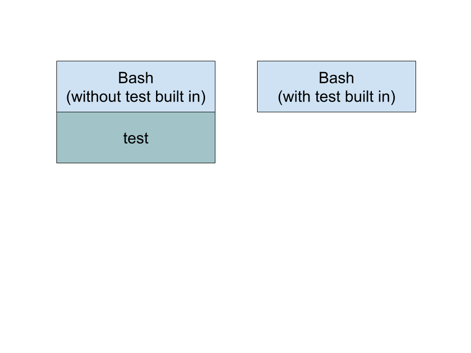
If you look at the bash manual, some things are built in and some are not. Using built ins ought to be faster than spawning a new program. For example, consider a line like:
if [ $a == $b ]
Some shells use a program named “test” to handle the square brackets. This causes a new program to launch. Modern bash provides this as a built in to help speed script execution and make it more efficient. However, you can disable it if you want to benchmark the difference. In general, you can disable a built in using “enable -n XXX” where XXX is the built in you want to disable. Use no options to enable it. Just entering the command with no arguments at all will give you a list of built in commands or use the -p option, if you prefer.
However, there’s more to it than that. If you have some common operation that takes a lot of overhead, you can write the code in a language such as C and ask the shell to load it as a shared object and then treat it as a built in. The technique is a little involved, but it shows the versatility of the shell. You can find an example that adds a few built in commands to bash in this article. For example, the code posted makes things like cat and tee part of the shell, as well as creating new commands.
Exotic Solutions
We’ll admit, that last solution is a bit exotic. However, there are other things you can do. You might create a persistent server and communicate with it using a named pipe to avoid running new code. When disks were slow, you could experiment with keeping frequently used programs on a RAM disk. Today, caching ought to do that almost automatically, but perhaps not in every scenario.
Sometimes just cleaning up your code can help. Imagine this:
cat "$1" | grep "$target"
This spawns two processes, one for cat and one for grep. Why not just say:
grep "$target" "$1"
Of course, the ultimate is to simply not use a shell script. Almost any programming language will have a richer set of things it can do without launching an external program. A compiled or semi-compiled language is likely to be faster and even will help you optimize.
Shell scripts are useful to a point. It is fun, too, to see just how far you can stretch them. However, if you are really that worried about efficiency or speed, this might be the best answer of all.
I was cooking this weekend when my eight-year-old son looked up from the couch, where he was listening to the Stardew Valley game soundtrack on Apple Music.
"Dad," he announced, "I'm going to read you the name of every song on this album."
Enlarge/ Chinese geneticist He Jiankui speaks during the Second International Summit on Human Genome Editing at the University of Hong Kong days after he claimed to have altered the genes of the embryo of a pair of twin girls before birth, prompting outcry from scientists of the field. (credit: S.C. Leung/SOPA Images/LightRocket via Getty Images)
On Monday, China's Xinhua News Agency reported that the researchers who produced the first gene-edited children have been fined, sanctioned, and sentenced to prison. According to the Associated Press, three researchers were targeted by the court in Shenzhen, the most prominent of them being He Jiankui. He, a relatively obscure researcher, shocked the world by announcing that he had edited the genomes of two children who had already been born by the time of his public disclosure.
He Jiankui studied for a number of years in the United States before returning to China and starting some biotech companies. His interest in gene editing was only disclosed to a small number of advisers, and his work involved a very small team. Some of them were apparently at his companies, while others were at the hospital that provided him with the ability to work with human subjects. After his work was disclosed, questions were raised about whether the hospital fully understood what He was doing with those patients. The court determined that He deliberately violated Chinese research regulations and fabricated ethical review documents, which may indicate that the hospital was not fully aware.
He's decision to perform the gene editing created an ethical firestorm. There had been a general consensus that the CRISPR technology he used for the editing was too error-prone for use on humans. And, as expected, the editing produced a number of different mutations, leaving us with little idea of the biological consequences. His target was also questionable: He eliminated the CCR5 gene, which is used by HIV to enter cells but has additional, not fully understood immune functions. The editing was done in a way that these mutations and their unknown consequences would be passed on to future generations.
Loads of folks find brand new Wyze surveillance cameras under their trees or in their stockings this Christmas. And on Boxing Day, the company itself unwrapped a whole new world of trouble for everyone who uses its products, confirming a data leak that may have exposed personal data for millions of users over the course of a few weeks.
Wyze first found out about the problem in the morning on December 26, company cofounder Dongsheng Song said in a corporate blog post. The company's investigation confirmed that user data was "not properly secured" and was exposed from December 4 onward.
The database in question was basically a copy of the production database that Wyze created to work with, Song explained. Data points left exposed include user email addresses, camera nicknames, WiFi network information, Wyze device information, some tokens associated with Alexa integrations, and "body metrics for a small number of product beta testers."
Your cellphone is the least secure computer that you own, and worse than that, it’s got a radio. [Jiska Classen] and her lab have been hacking on cellphones’ wireless systems for a while now, and in this talk gives an overview of the wireless vulnerabilities and attack surfaces that they bring along. While the talk provides some basic background on wireless (in)security, it also presents two new areas of research that she and her colleagues have been working on the last year.
One of the new hacks is based on the fact that a phone that wants to support both Bluetooth and WiFi needs to figure out a way to share the radio, because both protocols use the same 2.4 GHz band. And so it turns out that the Bluetooth hardware has to talk to the WiFi hardware, and it wouldn’t entirely surprise you that when [Jiska] gets into the Bluetooth stack, she’s able to DOS the WiFi. What this does to the operating system depends on the phone, but many of them just fall over and reboot.
Lately [Jiska] has been doing a lot of fuzzing on the cell phone stack enabled by some work by one of her students [Jan Ruge] work on emulation, codenamed “Frankenstein”. The coolest thing here is that the emulation runs in real time, and can be threaded into the operating system, enabling full-stack fuzzing. More complexity means more bugs, so we expect to see a lot more coming out of this line of research in the next year.
[Jiska] gives the presentation in a tinfoil hat, but that’s just a metaphor. In the end, when asked about how to properly secure your phone, she gives out the best advice ever: toss it in the blender.
Update: We're in the last throes of winter break 2019, which means most Ars' home office phones can stay dormant for a few more days. As such, we've been resurfacing a few classics from the archives—the latest being this look at how SIP (Session Initiation Protocol) won the VoIP protocol wars once upon a time. This story first appeared on December 8, 2009, and it appears unchanged below.
As an industry grows, it is quite common to find multiple solutions that all attempt to address similar requirements. This evolution dictates that these proposed standards go through a stage of selection—over time, we see some become more dominant than others. Today, the Session Initiation Protocol (SIP) is clearly one of the dominant VoIP protocols, but that obviously didn't happen overnight. In this article, the first of a series of in-depth articles exploring SIP and VoIP, we'll look at the main factors that led to this outcome.
A brief history of VoIP
Let's go back to 1995 in the days prior to Google, IM, and even broadband. Cell phones were large and bulky, Microsoft had developed a new Windows interface with a "Start" button, and Netscape had the most popular Web browser. The growth of the Internet and data networks prompted many to realize that it's possible to use the new networks to serve our voice communication needs while substantially lowering the associated cost. The first commercial solution of Internet VoIP came from a company called VocalTec; their software allowed two people to talk with each other over the Internet. One would make a local call to an ISP via a 28.8K or 36.6K modem and be able to talk with friends even if they lived far away. I remember trying out this software, and the sound was definitely below acceptable quality. (It frequently sounded like you were attempting to speak while submerged in a swimming pool.) However, the software successfully connected two people and introduced real-time voice conversation for a bandwidth-constrained network.


