Sunday, September 30

An Enigma Wrapped In A Riddle Wrapped In A Vintage Radio

Puzzle boxes are great opportunities for hacking. You can start with a box which was originally used for something else. You get to design circuitry and controls which offer a complex puzzle for the players. And you can come up with a spectacular reward for those who solve it. [thomas.meston’s] Dr. Hallard’s Dream Transmission Box, which he created for an original party game, has all those elements.

The box was a broken 1948 National NC-33 Ham Radio purchased on eBay after a number of failed bids. Most of it was removed except for the speaker. The electronics is Arduino based, so most of the smarts are in the form of code. Potentiometers and a switch provide the mechanism for players to enter codes. And when the correct code is entered, a relay triggers an external smoke machine and turns on a laser which illuminates a party ball, rewarding the victors. And of course, there are also sound effects as well as a recorded message.

We weren’t kidding when we said puzzle boxes make great hacks. Here’s one which ignites fireworks, one made only from discrete components, and a valentine based one which makes your significant other work for their gift.

California amends rules to push vehicles toward hydrogen, electricity, biofuel

Weekend Watch: Phun Kiss

A maker couple who collaborate on projects and document their efforts on YouTube.

Read more on MAKE

The post Weekend Watch: Phun Kiss appeared first on Make: DIY Projects and Ideas for Makers.

iCEstick Makes Terrible Radio Transmitter

We’ve done a lot of posts on how to use the Lattice iCEstick ranging from FPGA tutorials to how to use one as a logic analyzer. If you picked up one of these inexpensive boards here’s a fun little experiment. [T4D10N] saw a project [Hamster] put together to send SOS on the FM radio band using nothing but an FPGA. [Hamster used a Spartan], so he decided to do the same trick using an iCEstick with the open source IceStorm tools.

You might be surprised that the whole thing only takes 53 lines of Verilog — less if you cut out comments and whitespace. That’s because it uses the FPGA’s built-in PLL to generate a fast clock and then uses a phase accumulator divider to produce three frequencies on the FM radio band; one for a carrier and two for a tone, spaced 150 Hz apart. The result is really frequency shift keying but you can hear the results on an FM radio.

We know, we know. It is probably illegal to broadcast on the FM radio band in some places. however, unless you amplify the signal and use an antenna, this is basically radio frequency interference. The other thing is we couldn’t bear to send SOS no matter how faintly, so we changed the message string from:

 reg [33:0] message = 34'b1010100011101110111000101010000000;

to

reg [33:0] message = 34'b1010100011111111111000101010000000;

That makes it send “S long dash S” which, in some circles might be S0S (a long dash is sometimes used informally as a zero by straight key operators). The FPGA starts at the right and shift message over one spot each time beep_counter rolls over.

You can clearly hear the signal on 100 MHz, although the square wave is noisy sounding as you might expect. However, we bumped it down to 25 MHz and took a spectrum of it and it was better than we expected (see image above; the center line is 25 MHz and the scale is 5 MHz/division). Of course, that was admittedly a low bar to clear.

[Hamster’s] original code was in VHDL and for a Spartan 6. We’ve seen digital electronics generate RF before, of course. We’ve even seen it in color.

Tindie Guides That Hackaday Prize Entry Into Your Hands

Did lead poisoning finish off a doomed Arctic expedition?

The US would suffer some of the biggest costs of climate change

These 19th-century astronomical drawings show the beauty of cosmos

Étienne Léopold Trouvelot

We live in a golden age of astrophotography, with a feast of jaw-dropping images from the farthest reaches of space crossing our news feeds on a daily basis. But sometimes it's good to revisit the imagery of our pre-photographic past—in this case, the work of 19th-century illustrator Étienne Léopold Trouvelot. The Frenchman, once dubbed the "prince of observers," produced some 7000 astronomical illustrations over his lifetime, and we're featuring some of the best of them here.

Trouvelot was born in Aisne, France, but his political leanings put him at odds with Napoleon Bonaparte. After Napoleon's 1852 coup d'état, Trouvelot fled the country with his family in 1855 and landed in the Medford suburb of Boston, Massachusetts. Trained as an artist, nature illustrator, and printmaker, Trouvelot fell in love with astronomy after witnessing several auroras, and he began illustrating the amateur observations he spied through his small telescope.

Read 4 remaining paragraphs | Comments

Maker Faire NY: Getting Physical with Minecraft

If you’ve been hanging around Hackaday for a while, you’ve likely seen a few attempts to bridge the real world with the voxel paradise that is Minecraft. In the past, projects have connected physical switches to virtual devices in the game, or took chunks of the game’s blocky landscape and turned it into a 3D printable file. These were interesting enough endeavors, but fairly limited in their scope. They assumed you had an existing world or creation in Minecraft that you wanted to fiddle with in a more natural way, but didn’t do much for actually playing the game.

But “Physical Minecraft” presented at the 2018 World Maker Faire in New York, offered a unique way to bring players a bit closer to their cubic counterparts. Created by [Manav Gagvani], the physical interface has players use a motion detecting wand in combination with an array of miniature Minecraft blocks to build in the virtual world.

The wand even detects various gestures to activate an array of “Spells”, which are effectively automated build commands. For example, pushing the wand forward while making a twisting motion will automatically create a tunnel out of the selected block type. This not only makes building faster in the game, but encourages the player to experiment with different gestures and motions.

A Raspberry Pi 3 runs the game and uses its onboard Bluetooth to communicate with the 3D printed wand, which itself contains a MetaWear wearable sensor board. By capturing his own moves and graphing the resulting data with a spreadsheet, [Manav] was able to boil down complex gestures into an array of integer values which he plugged into his Python code. When the script sees a sequence of values it recognizes, the relevant commands get passed onto the running instance of Minecraft.

You might assume the wand itself is detecting which material block is attached to it, but that bit of magic is actually happening in the base the blocks sit on. Rather than trying to uniquely identify each block with RFID or something along those lines, [Manav] embedded an array of reed switches into the base which are triggered by the presence of the magnet hidden in each block.

These switches are connected directly to the GPIO pins of the Raspberry Pi, and make for a very easy way to determine which block has been removed and installed on the tip of the wand. Things can get tricky if the blocks are put into the wrong positions or more than one block are removed at a time, but for the most part it’s an effective way to tackle the problem without making everything overly complex.

We’ve often talked about how kid’s love for Minecraft has been used as a way of getting them involved in STEM projects, and “Physical Minecraft” was a perfect example. There was a line of young players waiting for their turn on the wand, even though what they were effectively “playing” was the digital equivalent of tossing rocks. [Manav] would hand them the wand and explain the general idea behind his interface, reminding them that the blocks in the game are large and heavy: it’s not enough to just lower the wand, it needs to be flicked with the speed and force appropriate for the hefty objects their digital avatar is moving around.

Getting kids excited about hardware, software, and performing physically demanding activities at the same time is an exceptionally difficult task. Projects like “Physical Minecraft” show there can be more to playing games than mindless button mashing, and represent something of a paradigm shift for how we handle STEM education in an increasingly digital world.

Ars vs. bugs round 2: We taste scorpions, meal worms, and ants

Watch the Snappy, Insect-like Moves of this DIY Quadruped Robot

Some legged robots end up moving with ponderous deliberation, or wavering in unstable-looking jerks. A few unfortunates manage to do both at once. [MusaW]’s 3D Printed Quadruped Robot, on the other hand, moves in rapid motions that manage to look sharp and insect-like instead of unstable. Based on an earlier design he made for a 3D printable quadruped frame, [MusaW] has now released this step-by-step guide for building your own version. All that’s needed is the STL files and roughly $50 in parts from the usual Chinese resellers to have the makings of a great weekend project.

The robot uses twelve SG90 servos and an Arduino nano with a servo driver board to control them all, but there’s one additional feature: Wi-Fi control is provided thanks to a Wemos D1 Mini (which uses an ESP-8266EX) acting as a wireless access point to serve up a simple web interface through which the robot can be controlled with any web browser.

Embedded below is a brief video. The first half is assembly, and the second half demonstrates the robot’s fast, sharp movements.

We love it when robots show some personality, like this adorable little quadruped robot that can make small jumps.

Thanks to [Baldpower] for the tip!

An SLA-Printed Pogo Pin Programming Jig

If you have a microcontroller to program, it can be an easy enough process to hook up a serial lead and perform the task. If however you have hundreds of microcontrollers on PCBs to program, connecting that lead multiple times becomes an impossibility. In manufacturing environments they have pogo pin jigs, an array of spring-loaded pins carrying the programming signals that line up perfectly with the appropriate pads on a PCB places on top of it.

[Conor Patrick] is working on an upgrade to the U2F Zero 2-factor authentication token, and he faces exactly this problem of needing to program a lot of boards. His pogo pin jig is very nicely executed, and he’s taken us through his design and manufacture process for it.

Starting with his PCB design in Eagle, he exported it to Fusion 360 in which he was able to create a jig to fit it. Into the jig model he placed the holes for his chosen pogo pins in the appropriate places, before printing it with an SLA 3D printer. He is particularly complementary about the pins themselves, a solder bucket design that comes from mill-Max, and was sourced via DigiKey.

The proof of the pudding is in the eating, and happily when his completed jig received its first board, everything worked as planned and the programming proceeded flawlessly. We’ve shown you other pogo pin jigs, but this one is particularly nicely executed.

This Nixie Device is Useless, But Pretty

Nixie clocks, they’re a bit of a cliché, aren’t they? But still, they’re pretty to look at.

[Marcin Saj] has completely got our number, and with his Useless Nixie Device has stripped away any pretence of functionality from his Nixie  and concentrated solely on the looking pretty part. It’s a box that steps through the display on any Nixie tube through the use of a set of pluggable socket modules, and it’s encased in an extremely attractive lase-cut acrylic enclosure. Internally it’s an extremely simple device, with a trusty 555 oscillator clocking a 4518 counter that in turn feeds 74141 driver. There is a MAX1771 boost converter in there too to create some high voltage for the tubes.

So it’s a pretty device and you can plug almost any Nixie into it given the right adapter. We guess it might be useful if you have a warehouse full of Nixies to test, but beyond that it’s a pretty desk toy. Still, it’s nice to see a Nixie project that’s not just another clock.

Putting M5Stack on LoRa and the Things Network

LoRa is the new hotness in low-power, long-range communications. Wanting to let the packets fly, [Xose] was faced with a frequecny problem and ended up developing a Europe-friendly LoRa module for the M5Stack system. The hardware is aimed at getting onto The Things Network, a LoRa based network that provides connectivity for IoT devices. While there was an existing M5Stack module for LoRa, it only supported 433 MHz. Since [Xose] is in Europe, an 868 MHz or 915 MHz radio was needed. To solve this, a custom board was built to connect the HopeRF RFM69 series of modules to the M5Stack.

If you haven’t heard of it before, the M5Stack platform is a stackable development board platform. Like Arduino, you can add functionality by stacking PCBs using a standard header. Unlike Arduino, M5Stack fits in a case nicely and is designed for building devices with user interfaces. For $35, you get an ESP32 based system with WiFi, Bluetooth, a color LCD, battery, buttons, a speaker, and IO connectors.

With the hardware in place, [Xose] 3D printed a custom case to hold the board and added it to the stack. The firmware acts as a monitor for The Things Network, showing live coverage. The final product looks very clean for a prototype, maintaining the finished look of M5Stack.

The firmware, board design, and case design files for the project are all available on Github.

Elon Musk settles fraud charge, he and Tesla to pay $40 million in penalties

Walk It Off, Healing Robots

Saturday, September 29

Gesture Control without Fancy Sensors, Just Pots and Weights

Turn a Cheap 3D Printer Into a Cheap Laser Cutter

We know it’s hard to hear it, but the days of you being a hotshot at the local Hackerspace because you’ve got a 3D printer at home are long gone. While they’re still one of the most persnickety pieces of gear on the hacker’s bench, they’re certainly not the rarest anymore. Some of these printers are so cheap now they’re almost impulse buys. Like it or not, few people outside of your grandmother are going to be impressed when you tell them you’ve got a personal 3D printer anymore; and we wouldn’t be surprised if even granny picked up a Monoprice Mini during the last open box sale.

But while 3D printer ownership isn’t the pinnacle of geek cred it once was, at least there’s a silver lining: cheap motion platforms we can hack on. [Dani Eichhorn] writes in to tell us about how he added a laser to his $200 USD Tevo Tarantula 3D printer, greatly expanding the machine’s capabilities without breaking the bank. The information in his write-up is pretty broadly applicable to most common 3D printer designs, so even if you don’t have a Tarantula it shouldn’t be too hard to adapt the concept.

The laser is a 2.5 W 445 nm module which is very popular with low-cost laser cutter setups. It’s a fully self-contained air cooled unit that just needs a source of 12 V to fire up. That makes it particularly well suited to retrofitting, as you don’t need to shoehorn in any extra support electronics. [Dani] simply connected it to the existing power wires for the part cooling fan he added to the Tarantula previously.

You may want to check the specs for your 3D printer’s control board before attaching such a high current device to the fan connector. Best case it just overloads the board’s regulator and shuts down, worst case the magic smoke might escape. A wise precaution here might be to put a MOSFET between the board’s fan output the and the laser, but we won’t tell you how to live your life. As far as laser safety, this device should probably work inside an opaque box, or behind closed doors.

Once the laser is hanging off the fan port of your printer’s controller, you can turn it on with the normal GCode commands for fan control, M106 and M107 (to turn it on and off, respectively). You can even control the laser’s power level by adding an argument to the “on” command like: M106 S30.

Then you just need to mount the laser, and it’s more or less business as usual. Controlling a laser engraver/cutter isn’t really that different from controlling a 3D printer, so [Dani] is still using OctoPrint to command the machine; the trick is giving it a “3D model” that’s just a 2D image with no Z changes to worry about. We’ve seen the process for doing that in Inkscape previously.

With this laser module going for as little as $60 USD (assuming you’ve got a 3D printer or two laying around to do the conversion on), this is a pretty cheap way to get into the subtractive manufacturing game. Next stop from there is getting one of those K40’s everyone’s talking about.

Tesla is outgrowing Elon Musk

Maker Faire NY: Cocoa Press Chocolate Printer

If you haven’t figured it out by now, the hype over desktop filament printers is pretty much over. But that doesn’t mean there aren’t new avenues worth exploring that use the basic FDM printer technology. If anything, the low cost and high availability of 3D printer parts and kits makes it easier to branch off into new territory. For example, experimenting with other materials which lend themselves to being “printed” layer by layer like a thermoplastic. Materials such as cement, clay, or even chocolate.

[Evan Weinstein] brought his Cocoa Press printer to the 2018 World Maker Faire in New York, and we have to say it’s a pretty impressive piece of engineering. Hackers have been known to throw a syringe-based paste extruder onto a regular 3D printer and try their luck with squirting out an edible object from time to time, but the Cocoa Press is truly a purpose built culinary machine.

Outwardly it features the plywood case and vaguely Makerbot-looking layout that we’ve seen plenty of times before in DIY 3D printers. It even uses the same RAMPS controller running Marlin that powers your average homebrew printer. But beyond these surface similarities, the Cocoa Press has a number of purpose-built components that make it uniquely qualified to handle the challenges of building with molten chocolate.

For one, beyond the nozzle and the walls of the syringe, nothing physically comes into contact with the chocolate to be printed; keeping the mess and chance of contamination to a minimum. The leadscrew actuated plunger used in common paste extruders is removed in favor of a purely air powered system: a compressor pumps up a small reservoir tank with filtered and dried air, and the Marlin commands which would normally rotate the extruder stepper motor are intercepted and used to trigger an air valve. These bursts of pressurized air fill the empty area above the chocolate and force it out of the 0.8 mm nozzle.

In a normal 3D printer, the “melt zone” is tiny, which allows for the heater itself to be relatively small. But that won’t work here; the entire chocolate load has to be liquefied. It’s a bit like having to keep a whole roll of PLA melted during the entire print. Accordingly, the heater on the Cocoa Press is huge, and [Evan] even has a couple spare heaters loaded up with chocolate syringes next to the printer so he can keep them warm until they’re ready to get loaded up.

Of course, getting your working material hot in a 3D printer is only half the battle, you also need to rapidly cool it back down if you want it to hold its shape as new layers are placed on top of it. A normal 3D printer can generally get away with a little fan hanging next to the nozzle, but [Evan] found the chocolate needed a bit of a chill to really solidify.

So he came up with a cooling system that makes use of water-cooled Peltier units. The cold side of the Peltier array is inside a box through which air is forced, which makes its way through an insulated hose up to the extruder, where a centrifugal fan and 3D printed manifold direct it towards the just-printed chocolate. He reports this system works well under normal circumstances, but unusually high ambient temperatures can overwhelm the cooler.

While “the man” prevented show goers from actually eating any of the machine’s creations (to give out food in New York, you must first register with the city), they certainly looked fantastic, and we’re interested in seeing where the project goes from here.

Root is a terrific—and fully asymmetric—woodland wargame

Facebook can’t be ordered to wiretap Messenger calls, judge rules

This arcade is really vintage: Visiting San Francisco’s Musée Mécanique

These 3D Printed Supports Can Take Hard Use, Thanks to Resin Filling

Drill Jig Helps Mount WeMos D1 Mini

As far as ESP8266 boards go, the WeMos D1 Mini is a great choice if you’re looking to get started with hackerdom’s microcontroller du jour. It’s small, well supported, and can be had ridiculously cheap. Often going for as little as $3 USD each, we buy the things in bulk just to have spares on hand. But that’s not to say it’s a perfect board. For one, it lacks the customary mounting holes which would allow you to better integrate it into finished products.

This minor annoyance was enough to spring [Martin Raynsford] into action. He noticed there was some open area on the D1 Mini’s PCB where it seemed he could drill through to add his own mount points, but of course popping holes in a modern PCB can be risky business. There’s not a lot of wiggle room between success and heartbreak, and it’s not like the diminutive D1 Mini is that easy to hold down to begin with. So he designed a laser-cut jig to allow him to rapidly add mounting holes to his D1 Mini’s assembly line style.

For those who might be skeptical, [Martin] reports he’s seen no adverse effects from drilling through the board, though does admit it’s possible the close proximity of the metal screw heads to the ESP8266’s antenna may have a detrimental effect. That said, he’s tested them in his projects out to 25 m (82 feet) with no obvious problems. He’s using a 2 mm drill bit to make his hole, and M2 x 6 mm machine screws to hold the boards down.

The jig design is released as a SVG and DXF for anyone with a laser cutter to replicate, but it shouldn’t be too difficult to extrude those designs in the Z dimension for hackers who haven’t yet jumped on the subtractive manufacturing bandwagon.

When a project makes the leap from prototype to in-house production, designing and building jigs become an essential skill. From flashing firmware to doing final checkout, the time and effort spent building a jig early on will pay for itself quickly in production.

Faux Aircon Units, Made Entirely From 2D Cuts

Creating Antimatter On The Desktop — One Day

If you watch Star Trek, you will know one way to get rid of pesky aliens is to vent antimatter. The truth is, antimatter is a little less exotic than it appears on TV, but for a variety of reasons there hasn’t been nearly as much practical research done with it. There are well over 200 electron accelerators in labs around the world, but only a handful that work with positrons, the electron’s anti-counterpart. [Dr. Aakash Sahai] would like to change that. He’s got a new design that could bring antimatter beams out of the lab and onto the desktop. He hasn’t built a prototype, but he did publish some proof-of-concept simulation work in Physical Review Accelerators and Beams.

Today, generating high-energy positron beams requires an RF accelerator — miles of track with powerful electromagnets, klystrons, and microwave cavities. Not something you are going to build in your garage this year. [Sahai] is borrowing ideas from electron laser-plasma accelerators (ELPA) — a technology that has allowed electron accelerators to shrink to mere inches — and turned it around to create positrons instead.

There are two stages. One creates a high-energy electron flux using the conventional a conventional ELPA process. This stage creates a shower or flux of electrons. The second stage is where things get interesting. The electron flux bounces off a metal target which causes them to decelerate. However, that additional energy has to go somewhere, so it creates a gamma ray. The gamma ray however is unstable and converts into a low-energy positron/electron pair. Those low-energy positrons can be formed into a high-energy beam.

Unlike conventional methods, the only large part of this accelerator design is the laser system which currently takes about 25 square meters of space. However, as the laser designs get better, it should eventually be possible to build such a device on the desktop. If that seems crazy, look at what’s happened with electron beam generation. SLAC using conventional methods can produce a 1 GeV beam in a 64 meter-long track. The record for ELPA is 4.25 GeV over 9 centimeters and a 2 GeV beam has been produced in equipment measuring 2 centimeters!

Does this mean we are going to finally get our Space Ranger antimatter pistol we always wanted? Maybe. Meanwhile, you might have to settle for just the laser. It seems like most of the big lasers we see anymore are relegated to cutting.

Bot Makes Etch A Sketch Art In One Continuous Line

Introduced in 1960 for the princely sum of $2.99 ($25.00 today), Etch A Sketch was to become a standard issue item for the Baby Boomers’ toy box. As enchanting as the toy seems, it’s hard to see why it had staying power: it was hard for young fingers to twirl the knobs, diagonal lines and smooth curves required a concert pianist’s fine motor control, and whatever drawings we managed to make were erased at the slightest jostle of the tablet.

Intent on righting these wrongs, [Sunny Balasubramanian] not only motorized an Etch A Sketch, but he’s also given it a mind of its own in a way. For those unfamiliar with the toy, it’s basically a manual X-Y plotter that drags a stylus across the underside of a glass screen, scraping off a silver powder clinging to the glass to make dark lines. Replacing the knobs with steppers is straightforward, of course, but driving them is the trick. [Sunny] hooked his up to a Raspberry Pi and wrote some Python code to drive them. The Pi also accepts input image files and processes them for rendering through the plotter, first doing Canny edge detection in OpenCV, then plotting a single path through the largest collection of connected pixels in the image. From there it’s just a matter of spinning the motors to create surprisingly detailed images. Check out the short video below to see it in action.

It’s hardly the first automatic Etch A Sketch we’ve seen – here’s one that automates everything including the shake to erase the drawing. That one cheats a little though, in that it rasters across the screen like a CRT. We really like how this one just does a single path. Pretty clever.


Friday, September 28

Microsoft suspends development of touch-friendly Office apps for Windows

Cloudflare gets into registrar business with wholesale domains and free privacy

Turns out, Nintendo created Bowsette before the Internet did

This month's last major Nintendo Direct video presentation included a reveal of another New Super Mario Bros. game—a Switch port of its last Wii U installment—with one curious twist. It includes a few new playable characters, and one of those, Toadette, can don a crown power-up and turn into a Toadette-Peach hybrid dubbed Peachette.

Fans didn't take long to imagine what might happen if other Mario series characters put that same crown on and transformed into Princess Peach hybrids, particularly Bowser. Thus, Bowsette was born in a wild flurry of detailed fan art (and we thank NintendoLife for this SFW gallery of examples). But as Nintendo itself revealed on Friday, fans' creation wasn't all that original... as Nintendo had already toyed with the idea itself.

A new official book from Nintendo, titled The Art of Super Mario Odyssey, premiered in Japan this week and offers a deep dive into concept art for the colorful 2017 game. On Friday, one of the book's buyers noticed a comic-styled storyboard within the book and posted the discovery on Twitter, as shown above. This hints at an idea that didn't make it into the final game: that Odyssey's primary gimmick, which allows Mario to become other creatures by hitting them with his "Cappy" hat, would also be used by Bowser.

Read 5 remaining paragraphs | Comments

Hidden fees that raise price of broadband would be banned by proposed law

Forza Horizon 4 is the best open-world driving game you can buy

Microsoft

After six years spanning three previous installments across two consoles, it's fair to say the Forza Horizon franchise is well established. This concept should sound familiar by now: an open-world driving game you can play solo or online, with a traveling music festival in the background. It's the work of Playground Games, built on the bones of the Forza game engine developed by Turn 10 for the even longer-running Forza Motorsport series. So far, the Horizon festival has visited Colorado, the Mediterranean, and Australia. And in Forza Horizon 4, it's Britain's turn.

If the developers at Playground were lazy, they could have just dusted off the last game and built a new map for it, replacing down under with the land soon to be known as Brexitopia. But the past two years have involved more than just building a new map. There's new online functionality with up to 72 players in a session. In addition to dynamic weather and days that turn into nights, now there are seasonal transitions, each of which brings new challenges for you to complete. There is a complete and welcome absence of loot boxes or microtransactions—something that will no doubt come as welcome news. And we even get a guest appearance from at least one other blockbuster game franchise.

Read 11 remaining paragraphs | Comments

Gaze Upon This Daft Punk Helmet’s Rows of Utterly Perfect Hand-Soldered LEDs

The iconic robot helmets of Daft Punk feature prominently as challenging DIY hardware projects in their own right, and the results never disappoint. But [Nathaniel Stepp]’s photo gallery of his own version really sets the bar in both quality and attention to detail. The helmet uses a Teensy 3.2 as the main processor, and the visor consists of 328 hand soldered through-hole APA106 addressable RGB LEDs. A laser cut panel serves as the frame for the LEDs, and it was heat-formed to curve around the helmet and mate into the surrounding frame. Each LED is meticulously hand-soldered, complete with its own surface mount decoupling cap; there’s no wasted space or excess wire anywhere to be seen. It looks as if a small 3D printed jig was used to align and solder the LEDs one or two columns at a time, which were then transferred to the visor for final connections with the power bus and its neighboring LEDs.

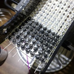
After the whole array was assembled and working, the back of each LED appears to have then been carefully coated in what looks like Plasti-Dip in order to block light, probably to minimize the blinding of the wearer. A small amount of space between each LED allows the eyeballs inside the helmet to see past the light show in the visor.

The perfectly done array of LEDs in the visor is just one of the design elements showing the incredible workmanship and detail in [Nathaniel]’s helmet. His website promises more build details are coming, but in the meantime you can drink in the details shown in the aforementioned photo gallery.

With Halloween approaching, you might be interested in rolling your own Daft Punk inspired helmet. Not ready to do everything from scratch? No problem, because it’s never been easier to make your own with the help of a 3D printer and some LED strips.

[via SparkFun Blog]

Tips of the Week: Analog Cutting of Digital Files, Cleaning Aged Plastic, Friction Welding, and Cough Drops

Another week of great tips, tricks, and useful kludges.

Read more on MAKE

The post Tips of the Week: Analog Cutting of Digital Files, Cleaning Aged Plastic, Friction Welding, and Cough Drops appeared first on Make: DIY Projects and Ideas for Makers.

Life is Strange 2, episode 1 review: New setting, same heart

50 million Facebook accounts breached by an access-token-harvesting attack

Give Yourself A Sixth Sense With An Arduino

International Energy Agency predicts wind will dominate Europe’s grid by 2027

Microsoft killing off the old Skype client… for real this time

Retrotechtacular: Here’s How They Programmed the EDSAC Computer

Boeing/Saab joint T-X design wins Air Force’s jet trainer competition

Maker Faire NY: Developing for the Final Frontier

The cost of getting a piece of hardware into space is now cheaper than ever, thanks in no small part to the rapid progress that’s been made by commercial launch providers such as SpaceX. In the near future, as more low-cost providers come online, it should get even cheaper. Within a few years, we could be seeing per kilogram costs to low Earth orbit that are 1/10th what they were on the Space Shuttle. To be sure, this is a very exciting time to be in the business of designing and building spacecraft.

But no matter how cheap launches to orbit get, it’ll never be cheaper than simply emailing some source code up to the International Space Station (ISS). With that in mind, there are several programs which offer students the closest thing to booking passage on a Falcon 9: the chance to develop software that can be run aboard the Station. At the 2018 World Maker Faire in New York we got a chance to get up close and personal with functional replicas of the hardware that’s already on orbit, known in space parlance as “ground units”.

On display was a replica of one of the SPHERES free-flying satellites that have been on the ISS since 2006. They are roughly the size of a soccer ball and utilize CO2 thrusters and ultrasonic sensors to move around inside of the Station. Designed by MIT as a way to study spaceflight techniques such as docking and navigation without the expense and risk of using a full scale vehicle, the SPHERES satellites are perhaps the only operational spacecraft to have never been exposed to space itself.

MIT now runs the annual “Zero Robotics” competition, which tasks middle and high school students with solving a specific challenge using the SPHERES satellites. Competitors run their programs on simulators until the finals, which are conducted using the real hardware on the ISS and live-streamed to schools.

We also saw hardware from “Quest for Space”, which is a company offering curricula for elementary through high school students which include not only the ground units, but training and technical support when and if the school decides to send the code to the matching hardware on the Station. For an additional fee, they will even work with the school to design, launch, and recover a custom hardware experiment.

Their standard hardware is based on off-the-shelf platforms such as Arduino and LEGO Mindstorms EV3, which makes for an easy transition for school’s existing STEM programs. The current hardware in orbit is setup for experiments dealing with heat absorption, humidity, and convection, but “Quest for Space” notes they change out the hardware every two years to provide different experiment opportunities.

Projects such as these, along with previous efforts such as the ArduSat, offer a unique way for the masses to connect with space in ways which would have been unthinkable before the turn of the 21st century. It’s still up for debate if anyone reading Hackaday in 2018 will personally get a chance to slip Earth’s surly bonds, but at least you can rest easy knowing your software bugs can hitch a ride off the planet.

Porsche debuts new $800,000 racer inspired by the iconic 935 Le Mans car

Porsche

For the second time in a few weeks, the Monterey area in California is playing host to an amazing automotive gathering. In August it was Car Week, probably the biggest gathering of rare classics and concepts on the planet. This week, it's the turn of just one marque, because it's Porsche's Rennsport Reunion. The event, held at WeatherTech Raceway Laguna Seca, is a celebration of Porsche's racing heritage over the past decades. And the car maker used the event to debut a new race car inspired by one of its greatest hits—it's a reborn 935.

The original 935 was a 911-based racer that first appeared in 1976 and went on to have an illustrious career in the late 1970s. Distinctive bodywork gave it a much wider track thanks to massively flared side extensions, a characteristic flat nose, and in the case of the 935/78 for the 1978 24 Hours of Le Mans, a massive whale tail at the rear. The last of those led to the car's enduring nickname: Moby Dick.

Read 3 remaining paragraphs | Comments

What 61,000 hidden structures reveal about Maya civilization

Inductance in PCB Layout: The Good, the Bad, and the Fugly

Apple’s watchOS 5.0.1 addresses bug that may prevent Watches from charging

Review: Google’s Wear OS 2.0 can’t fix its obsolete smartwatch hardware

Incredible Star Trek: The Next Generation simulation ordered to stand down

Crushing Cars Like Empty Cans With The Massive “Hand Of Man”

see Katelyn lift a car in the air like a maniac

Read more on MAKE

The post Crushing Cars Like Empty Cans With The Massive “Hand Of Man” appeared first on Make: DIY Projects and Ideas for Makers.

California Apple store robbery gang stole over $1M in goods, cops say

A decades-old pollutant is still threatening orca populations

Rocket Report: 10 years since Falcon 1, Stratolaunch engine, hybrid rocket

FPGA Jacked Into Pinball Machine Masters High Scores

How do you preserve high scores in an old arcade cabinet when disconnecting the power? Is it possible to inject new high scores into a pinball machine? It was the b-plot of an episode of Seinfield, so it has to be worth doing, leading [matthew venn] down the rabbit hole of FPGAs and memory maps to create new high scores in a pinball machine.

The machine in question for this experiment is Doctor Who from Williams, which, despite being a Doctor Who pinball machine isn’t that great of a machine. Still, daleks. This machine is powered by a Motorola 68B09E running at 2MHz, with 8kB of RAM at address 0x0000. This RAM backed up with a few AA batteries, and luckily is in a DIP socket, allowing [matthew] to fab a board loaded up with an FPGA development board that goes between the CPU and RAM.

The basic technique for intercepting and writing a new high score for this pinball machine comes from the incredible [sprite_tm] who is tweeting high scores from a 1943 cabinet. The idea is simple: just have an FPGA look at one specific memory address, and send some data to a computer when the data at that address is updated. For the Doctor Who pinball machine, this is slightly harder than it sounds: the data isn’t stored in hex, but packed BCD. After a little bit of work, though, [matthew] was able to write new high scores from a Python script running on a laptop. All the code (and a few more details) are over on a Github

Extending arcade games by tapping into address and data lines isn’t something we see a lot of, but it has been done, most famously with the Church of Robotron. Here, a few MAME hacks turn a game of Robotron into a Church for the faithful to fully commit themselves to the savior of the world, due to arrive in 66 years and save the remaining humans from the robot apocalypse. This hack of a Doctor Who pinball machine goes beyond a modded version of MAME, and if we’re ever going to make a real chapel with a real game of Robotron, these are the techniques we’re going to use.

What pushed 2017’s Atlantic hurricane season into overdrive?

Sounding A Sour Note Can Save People From A Sour Stomach (Or Worse)

We’ve covered construction of novel music instruments on these pages, and we’ve covered many people tearing down scientific instruments. But today we’ve got something that managed to cross over from one world of “instrument” into another: a music instrument modified to measure a liquid’s density by listening to changes in its pitch.

This exploration started with a mbira, a mechanically simple music instrument. Its row of rigid metal tines was replaced with a single small diameter hollow metal tube. Filling the tube with different liquids would result in different sounds. Those sounds are captured by a cell phone and processed by an algorithm to calculate the difference in relative density of those liquids. Once the procedure was worked out, the concept was verified to work on a super simple instrument built out of everyday parts: a tube mounted on a piece of wood.

At this point we have something that would be a great science class demonstration, but the authors went a step further and described how this cheap sensor can be used to solve an actual problem: detecting counterfeit pharmaceuticals. Changing composition of a drug would also change its density, so a cheap way to compare densities between a questionable sample against a known good reference could be a valuable tool in parts of the world where chemistry labs are scarce.

For future development, this team invites the world to join them applying the same basic idea in other ways, making precise measurements for almost no cost. “Any physical, chemical, or biological phenomena that reproducibly alters the pitch-determining properties of a musical instrument could in principle be measured by the instrument.” We are the ideal demographic to devise new variations on this theme. Let us know what you come up with!

If you need to do quick tests before writing analysis software, audio frequency can be measured using the Google Science Journal app. We’ve seen several hacks turning a cell phone’s camera into instruments like a spectrometer or microscope, but hacks using a phone’s microphone is less common and ripe for exploration. And anyone who manages to make cool measurements while simultaneously making cool music will instantly become a serious contender in our Hackaday Prize music instrument challenge!

[via Science News]

From Oakland to Ottawa: The Serpent Twins Bring Their Magic to Canada

The 50-foot Serpents have made the pilgrimage to the Canadian capital for the 7th annual Maker Faire Ottawa this weekend.

Read more on MAKE

The post From Oakland to Ottawa: The Serpent Twins Bring Their Magic to Canada appeared first on Make: DIY Projects and Ideas for Makers.

Antennas That You Install With A Spray-Can

With the explosion in cell phones, WiFi, Bluetooth, and other radio technologies, the demand for antennas is increasing. Everything is getting smaller and even wearable, so traditional antennas are less practical than ever. You’ve probably seen PCB antennas on things like ESP8266s, but Drexel University researchers are now studying using titanium carbide — known as MXene — to build thin, light, and even transparent antennas that outperform copper antennas. Bucking the trend for 3D printing, these antennas are sprayed like ink or paint onto a surface.

A traditional antenna that uses metal carries most of the current at the skin (something we’ve discussed before). For example, at WiFi frequencies, a copper antenna’s skin depth is about 1.33 micrometers. That means that antennas have to be at least thick enough to carry current at that depth from all surfaces –practically 5 micrometers is about the thinnest you can reasonably go. That doesn’t sound like a lot, but when you are trying to make something thin and flexible, it is pretty thick. Using MXene, the researchers made antennas as thin as 100 nanometers thick — that’s 10% of a micrometer and only 2% of a conventional antenna.

There are other materials that wind up in thin antennas, but they all have challenges either because they are not very conductive or are difficult to fabricate. MXene is a fairly new family of materials developed at Drexel University. To produce it you start with MAX which is a combination of titanium, aluminum, and carbon. The aluminum is removed in a process that requires acid and stirring for 24 hours, lithium chloride, and a centrifuge. The hydrofluoric acid is nasty to work with, but not beyond the reach of a careful home lab. You can see a Drexel video about making MXene, below. The researchers sprayed the antennas on a thin plastic substrate.

The only thing that looked tricky to us, was that thin flakes of the specific MXene used degrade in the air due to oxidation. That means production needs argon gas and the final product has to be laminated with something to protect it from the air, so that’s going to add thickness in a practical device.

Of course, PCB antennas are nothing new. But if you read the paper, you’ll see these antennas can readily outperform conventional thin antennas.

Three Part Deep Dive Explains Lattice iCE40 FPGA Details

It is no secret that we like the Lattice iCE40 FPGA. It has a cheap development board and an open source toolchain, so it is an easy way to get started developing low-cost, low-power FPGA designs. There are a few members of the family that have similar characteristics including the top-of-the-line UltraPlus. [Steve] from Lattice and [Michael Klopfer] from the University of California Irvine have a three-part video series that explain the architecture of the devices. Altogether, the videos are about an hour long and — of course — they use the official tools, not IceStorm. But it is still a great time investment if you have an iCE40 board and you want to understand what the chip has under the hood.

The first part is fairly short and talks a lot about applications. There’s also a nod to the hobbyist use of FPGAs. Keep in mind that the iCE40 FPGAs come in different sizes and variants, so don’t get excited when you see them mention a RISC-V — that isn’t going to fit in your iCEStick, that we know of. The iCEstick has a HX-1K onboard, which is the high-performance variant with 1,280 logic elements, as opposed to the low-power (LP) version.

In fact, you might want to watch the video with the datasheets open. The lowest-end UltraPlus device has more logic elements (2,800 vs 1,280) and more RAM (1,104 kbits vs 64 kbit). It also has specialized I2C, SPI, DSP, and PWM hardware onboard. While the HX-1K lacks those extra features, it does allow 98 I/Os maximum compared to the low-end UltraPlus’ 21 I/O. They also have lower maximum propagation delays which means you can usually get them to clock faster than other members of the family.

However, the core fabric is the same: a four-input lookup table (LUT4), a D flip-flop, and some carry logic. More modern FPGAs will often have more inputs to the LUTs to provide denser packing, so be careful comparing one FPGA family’s cell count to another.

Of course, if you are using the iCEstick, you may want to graduate to the more powerful family members and then everything in the videos will apply. They use the UpDuino which is a good upgrade and still very inexpensive. The third video covers the Lattice-specific tools. Be aware that if you want to use the Ultra or UltraPlus devices that Icestorm only supports some of them. If you do use IceStorm, you’ll want to read about the support for newer devices. If you haven’t gotten started with FPGAs yet, why not head over to Hackaday.io and learn more about using the iCE40 in the FPGA bootcamps?

Sorting LEGO Is Like Making A Box Of Chocolates

Did you know that chocolate candy production and sorting LEGO bricks have something in common? They both use the same techniques for turning clumps of chocolates or bricks into individual ones moving down a conveyor belt. At least that’s what [Paco Garcia] found out when making his LEGO Sorter.

Sorting LEGO bricks using guidesHowever, he didn’t find that out right away. He first experimented with his own techniques, learning that if he fed bricks to his conveyor belt by dropping a batch of them in a line perpendicular to the direction of belt travel then no subsequent separation attempt of his worked. He then turned to [akiyuky’s] LEGO sorter for inspiration and dropped them onto the belt at an angle, ensuring that some bricks would be in front of others. A further trick he found is very well demonstrated in the chocolate sorting video below and shown in the image here. That is to use guides on the belt which serve to create speed differentials. Bricks move slower than the conveyor belt while pressed against a guide but when a brick leaves the guide, it accelerates to the speed of the conveyor belt, pulling away from the bricks still at the guide and thus separating them.

A further discovery had nothing to do with chocolate production, unless maybe for quality control. Once an individual brick had been separated out, it had to be classified. To do that he used Google’s Inception v3 neural network. But first, he had to retrain it for recognizing different types of LEGO bricks, something we’ve seen done before for use with recognizing playing cards. And to do the retraining, he needed many images of different bricks all separated into their different types. That’s where he came up with a clever trick. He used his own sorter for that. For example, to get a bunch of images of 1×1 bricks of different colors and orientations, he simply ran them through the sorter, saving the images to files and assigning them to the 1×1 brick class. He then used his desktop machine with a GeForce GT 730 GPU for the retraining, taking around 2.7 seconds per brick. For sorting though, he runs the trained neural network on a Raspberry Pi, taking 3.8 seconds for each brick. The resulting sorter works quite well, sorting with 89% accuracy. Watch it in action in the video below.

[via adafruit]

Thursday, September 27

E-Voting researchers warn of hack that could “flip the Electoral College”

Carmack: Oculus Quest’s power is comparable to Xbox 360 or PS3

Google backtracks—a bit—on controversial Chrome sign-in feature

Last year’s flu was brutal—killing 80,000—but vaccine did better than expected

SEC sues Elon Musk over “funding secured” tweets

Amazon’s Jeff Bezos will now sell rocket engines, too

RTL-SDR Paves Way To Alexa Controlled Blinds

You’d be forgiven for occasionally looking at a project, especially one that involves reverse engineering an unknown communication protocol, and thinking it might be out of your league. We’ve all been there. But as more and more of the devices that we use are becoming wireless black boxes, we’re all going to have to get a bit more comfortable with jumping into the deep end from time to time. Luckily, there are no shortage of success stories out there that we can look at for inspiration.

A case in point are the wireless blinds that [Stuart Hinson] decided would be a lot more useful if he could control them with his Amazon Alexa. There’s plenty of documentation on how to get Alexa to do your bidding, so he wasn’t worried about that. The tricky part was commanding the wireless blinds, as all he had to go on was the frequency printed on the back of the remote.

Luckily, in the era of cheap RTL-SDR devices, that’s often all you need. [Stuart] plugged in his receiver and fired up the incredibly handy Universal Radio Hacker. Since he knew the frequency, it was just a matter of tuning in and hitting the button on the remote a couple times to get a good capture. The software then broke it down to the binary sequence the remote was sending out.

Now here’s where [Stuart] lucked out. The manufacturers took the easy way out and didn’t include any sort of security features, or even bother with acknowledging that the signal had been received. All he needed to do was parrot out the binary sequence with a standard 433MHz transmitter hooked up to an ESP8266, and the blinds took the bait. This does mean that anyone close enough can take control of these particular blinds, but that’s a story for another time.

We took a look at the Universal Radio Hacker a year or so back, and it’s good to see it picking up steam. We’ve also covered the ins and outs of creating your own Alexa skills, if you want to get a jump on that side of the project.

Dept. of Justice cracks down on another multimillion dollar biofuel fraudster

Dealmaster: Get an eight-core AMD Ryzen 7 2700 processor for $220

The Redox Keyboard

Robocaller spoofed real numbers to avoid angry call-backs to his own phone

Laser Noob: Getting Started With the K40 Laser

Why spend thousands on a laser cutter/engraver when you can spend as little as $350 shipped to your door? Sure it’s not as nice as those fancy domestic machines, but the plucky K40 is the little laser that can. Just head on down to Al’s Laser Emporium and pick one up.  Yes, it sounds like a used car dealership ad, but how far is it from the truth? Read on to find out!

Laser cutting and engraving machines have been around for decades. Much like 3D printers, they were originally impossibly expensive for someone working at home. The closest you could get to a hobbyist laser was Epilog laser, which would still cost somewhere between $10,000 and $20,000 for a small laser system. A few companies made a go with the Epilog and did quite well – notably Adafruit used to offer laptop laser engraving services.

Over the last decade or so things have changed. China got involved, and suddenly there were cheap lasers on the market. Currently, there are several low-cost laser models available in various power levels. The most popular is the smallest – a 40-watt model, dubbed the K40. There are numerous manufacturers and there have been many versions over the years. They all look about the same though: A blue sheet metal box with the laser tube mounted along the back. The cutting compartment is on the left and the electronics are on the right. Earlier versions came with Moshidraw software and a parallel interface.

The K40 mechanics haven’t changed very much, but the electronics have been updated to USB with modern stepper drivers. Make no mistake, these are not “quality” machines. They are built down to a cost. Interlock switches are non-existent. Overheat protection for the tube is your problem. Low cooling water flow alarm? Nope, better keep an eye on that yourself. The cutting bed looks like a mixture of an afterthought and parts someone found in the spares bin. The exhaust duct is routed 3 inches into the cutting area. In other words, these are the perfect machines for a hacker.

I’ve been watching the K40 and similar machines on eBay for years. Originally these machines were shipped from China. It was a crapshoot if a large heavy gas filled glass tube would survive the trip halfway around the world. Now, many of the machines are shipping from California and other ports within the lower 48 states. I’m guessing the machines are shipped to a warehouse here in the USA, tested, then the good units are sent on to customers.

With all this in mind, I finally decided to jump in and get a K40 laser. My first problem was deciding which laser to buy. eBay and Alibaba are riddled with auctions from sellers with different versions of the K40. Everyone says they’re newer and better than the rest. Some boast different accessory packages, and things like air assist – but also cost more. There is enough information to throw even the most seasoned eBayer into analysis paralysis mode.

In the end, I decided to go with one of the cheaper (but not the cheapest) lasers with a digital front panel display. My model also came with a temperature readout for the cooling water, and wheels – for those who like to roll their benchtop lasers around.

I clicked the “buy it now” button and started waiting. The machine in its 62 lb crate would take about a week to ship from the west coast. That gave me plenty of time to order some safety equipment.

Laser Safety

While the K40 may be cheap, I didn’t want to skimp on safety equipment. There are many vendors for laser safe goggles online. There are plenty of them available from China, but I really didn’t want to risk my eyes to a company I had never heard of. I did some checking around and ended up ordering a pair manufactured by Honeywell. Amazon had them available on Prime, so they got to me before the K40 itself. Whichever pair you order, make sure they are rated for CO2 lasers. There are many types of lasers out there, and goggles meant to protect you from a UV medical laser won’t help much at all when it comes to an IR laser like the one in the K40. IR safe glasses will be clear, or nearly so. But don’t mistake them for bog standard safety glasses. These are specially made materials which will help keep you safe from the invisible blindness beam your K40 puts out when your other safety measures fail.

Lasers burn things, and it is unfortunately common for those things to catch fire inside the laser. I’m keeping a large ABC dry powder fire extinguisher near the printer. However, that’s only a stopgap. If you’ve ever had to use a powder extinguisher, you know how messy they are. To try to keep the K40 and the rest of my lab safe, I’m planning to invest in a gas extinguisher of some type. Either CO2 or Halotron, depending on which is safer for use in a basement room.

While I never plan to leave the laser running unattended, I also have smoke detectors in my lab. Finally, I added a carbon monoxide detector to make sure the K40 doesn’t fill the room with a silent killer.

Unboxing

Hackaday doesn’t do unboxing videos, but the impression I got while unpacking the K40 was that it is big – bigger than one would imagine from the photos. My machine measured 32″ wide x 19.75″ deep x 10.25″ high. Thankfully I had workbench space right near a window that made a perfect home.

Cooling

The K40 laser is water cooled. All the lasers include a coolant pump as one of the accessories. The pump I received is a wonder of cost reduction. It’s an aquarium or pond pump, with a magnetically coupled impeller. I was concerned when after use I saw water dripping out of the pump down the 120 V power cord. It turns out the back cover of the pump isn’t even sealed. It doesn’t need to be. The motor stator and coils are potted in black epoxy. As long as that potting compound is in place, nothing can get to the motor. It does seem to work well for keeping the cooling water flowing. However, I can’t say I completely trust it with the life of my laser tube. A mod may be in the future for this system.

For coolant, I’m using distilled water. My reservoir for these early tests is a simple shoebox-sized plastic container. It holds a gallon of water and keeps the pump submerged. If the laser isn’t going to be used for a few days, I dump the water and empty the tube by blowing into the inlet line.

Exhaust

Cutting things with a laser will produce smoke and fumes; that’s a given. The K40 comes with an exhaust fan which is rather anemic, to say the least. It’s literally a bathroom exhaust fan slapped on the back of the laser. Smoke is pulled through a slot cut in the back of the case and sent up the exhaust hose. I already have a large Dayton fan mounted in the window of my lab. While the unguarded blades are decidedly dangerous, it moves a crazy amount of air. This coupled with the stock exhaust fan was able to keep the smell of burning wood and plastic down to reasonable levels. However, I’ll definitely be upgrading the stock exhaust in the future.

Aligning The Optics

The first step in setting up one of these lasers is arguably the most dangerous: aligning the mirrors. This is why I bought good laser goggles. Working on the laser with the doors off is something you generally don’t want to do since you can’t control where the beam goes.

Keep the laser safety glasses on at all times, close the door, and make sure no one else walks into the room. My tube was so far out of alignment that the beam exited the case through the open door and made a small scorch mark on the wall behind my workbench. It would not have been good if someone else was standing there.

There are plenty of video tutorials out there for aligning the mirrors on a K40. I found this one to be particularly helpful. The idea is to make sure that the laser dot hits the center of each of the three mirrors in the beam path. Two of the mirrors move on an X-Y table, so it’s important to make sure the beam hits the same spot no matter where they are positioned. I used Post-it notes rather than the painter’s tape many of the tutorials call for. It’s much easier to see the burn mark on the yellow Post-It than on the dark blue tape.

You don’t need a computer for these steps, just keep the stepper motors off and move the table by hand. When it comes time to fire the laser, you just have to tap the test button on the front panel.
The first thing to align is the tube itself. My tube was so far out of alignment that the beam wasn’t even hitting the mirror. The tube is held in with two metal spring straps. Rubber rings keep the straps from breaking the glass tube. More rubber acts as shims to align the tube vertically. I removed one of the shims from the left side of the tube and added it to the right. It’s a fiddly procedure since tightening too hard on the screws will break the single most expensive part of the K40 – the laser tube.

I found that even after an alignment, my K40 still wasn’t performing correctly. I cleaned the mirrors and the laser tube with alcohol, but it was no help. Finally, I disassembled the focusing head. That’s where I found my problem. There were bits of metal inside the head from when it was machined. These metal pieces were in the beam path, disrupting it. I took the 45-degree mirror and the focusing lens out, then carefully cleaned the tube. Once everything was re-assembled, my K40 was ready for action.

Software

The laser comes with an obviously burned CD and a USB stick. My laptop doesn’t have a CD drive, so I popped in the USB stick and found… nothing. It’s not really a drive, but a dongle to unlock the laser driver software. I had to go and find my USB cd drive before using the K40. Most of the filenames on the disc are in Chinese. Some digging eventually led me to a file for Corel Laser. It’s a copy of Corel Draw with a plugin to drive the K40. The copy of Corel Draw is almost certainly an illegal cracked copy. I got access to a legit base copy from a friend who switched over to Adobe.

In simple terms, CorelLaser gives you a toolbar and can cut or engrave any image loaded into Corel Draw. Cutting and engraving are very different processes though. Cutting is a vector operation. The laser will trace the path of every line in the image. Engraving is a raster affair. The laser will draw the image line by line, left to right and top to bottom. You can also perform both processes on the same design by creating a cut layer and an engraving layer in the software.

I ran into trouble with the software pretty quickly. Whenever I tried to cut, the laser head moved slowly. Changing the movement settings didn’t help. Some digging eventually pointed me to the settings page for CorelLaser. Here I found the “mainboard” setting was wrong. The value has to match the model number silk screened on the laser mainboard. Of course, the mainboard is mounted in such a way that you can’t read the model number, but a quick cell phone photo fixed that problem. My model is 6C6879-LASER-M2. The board firmware is dated 2018-01-08, so the board must have been built sometime after that.

I expected CorelLaser to be a hot mess. Honestly, it isn’t half bad. It definitely has some maddening quirks, but overall it does what it should – drive the steppers and switch the laser. The top quirk I’ve found is line width. Corel defaults to “hairline” as line width. This is larger than the laser kerf, so CorelLaser interprets it as two parallel paths. Tracing two close paths on with the K40 will make a wide burning mess of whatever you’re trying to cut. The solution is to select everything in your document <Ctrl-A> then hit F12, and change the line width to .001 mm. CorelLaser will then operate as you expect it to.

Which Materials to use (and which to avoid)

What to cut? As with any laser cutter, thought has to be given to the materials being cut. In general, wood is safe to cut, as is paper, cloth, melamine, pressboard, matte board, cork, some rubbers, natural leather, and Corian. Engraving can be performed on materials such as glass, stone, anodized aluminum, steel (with a laser engraving coating) and other materials.

Some plastics should never be cut in a laser cutter. Anything with chlorine – notably PVC and vinyl. Burning PVC results in chlorine gas, which will kill the user, and hydrochloric acid, which will rust your K40 out so bad that your next of kin won’t be able to enjoy it. A simple test for chlorine is the copper wire burnination test, which can be seen in this 10-year-old video from [Adam] and [Zach] at NYC Resistor. ABS plastic is another one to avoid. It tends to melt and is messy to cut. It also releases trace amounts of cyanide gas. If you’re ever unsure about a material, look up on the pages of hackerspaces who have lasers. If they won’t cut it on their laser, you probably shouldn’t either.

Cutting and Engraving

Cutting and engraving are what we’re all here for, right? The fun part of learning the laser is figuring out how to set up the software for different materials. With a laser, you have three variables to play with. Laser power, speed, and the number of passes. Laser power is controlled by the front panel of the K40. It’s either a knob and an inaccurate milliampere meter or a digital control expressed in power percentage. Cutting with more than one pass is messier than just cutting the material once, so save that for when you really need to do it.

There are a few guides out there – I’ve found this page to be a good starting point for figuring out which speeds and power levels to run at for a given material. I generally will use the speed from that site, then start at a much lower laser power. Testing on scrap pieces, I’ll keep raising the power until I have a clean cut. If the power is below 50%, I’ll generally stick with it, and not adjust the speed.

You should definitely keep notes of what you use. On my laser, I found a deep engrave on ⅛” acrylic at 50% and 320 mm/s. Cutting ⅛” birch plywood worked best at 25% power and 5 mm/s. Keep in mind that quality control on the K40 is non-existent, and beam focus will matter, so your device may be different from mine. Further, materials such as plywood and acrylic can change from batch to batch depending on moisture content and other variables. Always buy some extra material to use as scrap for dialing in your settings.

Performance

So how good is the K40 in a “bone stock” condition? Pretty damn good actually. I was able to cut ⅛” birch plywood and ⅛” acrylic with one pass at less than 50% power. The parts would literally fall out as each cut complete. This is a laser, so of course, there is some charring of the wood on the edges, but nothing a bit of sandpaper can’t fix. As a torture test, I took the Hackaday logo .svg file loaded it up into CorelLaser, set the line width to .001 mm, and hit go. The K40 dutifully cut out the jolly wrencher, giving me a little puzzle of pieces to try to fit back together.
Engraving performance was good too – I was able to cut simple black and white images (and text) into wood and acrylic. I can see how this would be perfect for making control panels with labeled lights and switches.

Summary

The K40 is a cheap laser engraver/cutter. However, it is very capable, even when used unmodified. That said, the cutter is a great platform for modification. You can bet I’ll be spending some time adding things like air assist and a better bed to my K40 as well as cutting down that exhaust duct.