Monday, December 30

Parallel Pis for Production Programming; Cutting Minutes and Dollars Off of Assembly

Assembly lines for electronics products are complicated beasts, often composed of many custom tools and fixtures. Typically a microcontroller must be programmed with firmware, and the circuit board tested before assembly into the enclosure, followed by functional testing afterwards before putting it in a box. These test platforms can be very expensive, easily into the tens of thousands of dollars. Instead, this project uses a set of 12 Raspberry Pi Zero Ws in parallel to program, test, and configure up to 12 units at once before moving on to the next stage in assembly.

Fixing Fixture Bottlenecks

The company where I work, Propeller Health, develops IoT products that are assembled in a way similar to many other companies; there is a circuit board and a plastic enclosure. The bare PCBs go through SMT twice (components on the front and back), then they go through ICT (In-Circuit Test) where they are programmed and pogo pins on each of the test points verify all components on the circuit. They are also given a unique MAC address for Bluetooth based on a 2D barcode sticker placed on the board after SMT. After that they are assembled into the plastics and run through a functional test fixture before they are put into inventory mode and boxed. We have a product line of around a dozen different devices, and each uses a different PCB and enclosure.

Production runs need test and programming fixtures, a topic i wrote about a few years ago. To increase scale and reduce costs we started working more closely with our contract manufacturer to identify and fix the bottlenecks in the assembly line process, and we noticed that the ICT stage was taking 6 minutes for a panel of 6 boards. The ICT section itself was relatively fast, but the firmware programming and mac programming were taking a long time because the test platform was not capable of multiple simultaneous serial port connections.

This was a $30k fixture with 6 Segger programmers, 6 Keysight scanners, sitting on top of a $100k Teradyne platform, and it was our biggest bottleneck and greatest expense. Further, each device in our product line requires different fixturing. The combination of these expensive fixtures and slow cycle time was making our COGS (Cost Of Goods Sold) untenable.

On an assembly line, time is literally money, as every cycle time for every operator on the line is measured and added to the cost of the product. Reducing a cycle by even a second adds up quickly over a volume of thousands. Over 10k units, 2 second reduction is 6 hours of labor, at $15/operator hour is $.01/unit, and CMs, especially US based ones, are charging more than $15/hour. Having a 6 minute cycle time for 6 pieces was ripe for improvement.

Stage One – Arduino

The first stage was more a proof of concept. Could we pull some of the functionality off of the expensive ICT fixture onto a cheaper faster fixture so that we could scale in serial instead of buying another fixture to scale in parallel?

For this stage we implemented a feature in our firmware we call self-test, which is similar to a JTAG boundary scan. Rather than placing pogo pins on every net, we put a feature into the firmware to run a self-test on as many components as it could, and report the results over serial. This way we’d be able to connect only with the power and UART pins and get a complete and very fast readout of what exactly failed. Eight Arduinos connected via a USB hub to a tablet PC with a custom Python script and interface was the solution.
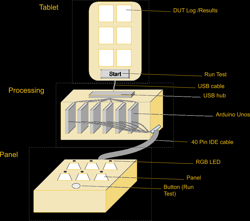
Diagram of the self-test fixture.

A single 40pin IDE connector was enough to have power, an RGB LED, RX, TX, and a single button that would kick off the cycle for all 8 at once. The Arduino would request a self-test from the DUT (Device Under Test), which would test its components and report back. Tests included verifying that sensors were reading values within an expected range, but also turning on the LED and buzzer and measuring the voltage drop to verify that outputs worked as well.
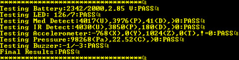
The microcontroller executes a series of tests on its own components and verifies they are within preset ranges, then reports success or failure.

This worked, and proved the concept of creating a box with most of the electronics paired with a simple customized fixture for the panel, but it wasn’t enough. Pulling out some of the circuit tests was insufficient to reduce time significantly. We needed to pull out more tasks.

Stage Two – Raspberry Pi

One of the more expensive parts of the ICT fixture was the Segger J-Link programmers. If we could pull out programming from ICT with something cheaper, we could reduce fixture costs significantly. Many chip manufacturers offer programming at the factory so that your microcontrollers come on a reel with your firmware pre-programmed. This is useful when you don’t trust your manufacturer or don’t want to have a special fixture for programming, but it does have an added cost, and there’s a lead time, and changing your firmware is more difficult, and you can’t use that part on any other product.

Programming in house had a lot of appeal for us, simplified our supply chain, and gave us more flexibility to change our firmware and shift inventory as needed. Enter the Raspberry Pi Zero W and OpenOCD. The Raspberry Pi is more than capable of running OpenOCD to program a microcontroller, and was surprisingly easy to configure and get running. It also had a serial port and GPIO for controlling WS2812B LEDs, and was small enough that it was easy to put a bunch in a box.
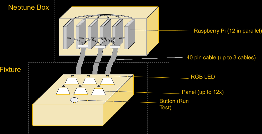
Block Diagram of Neptune

The connector expanded to a second 40pin IDE cable, and support for up to 12 parallel units, the size of our largest panels. Each Pi runs completely independently, without communicating with each other. The only thing they have in common (besides power supply) is that all 12 are connected to the same pushbutton on the front of the fixture. The button is used by the operator to start the programming cycle, but each Pi runs its process independently.
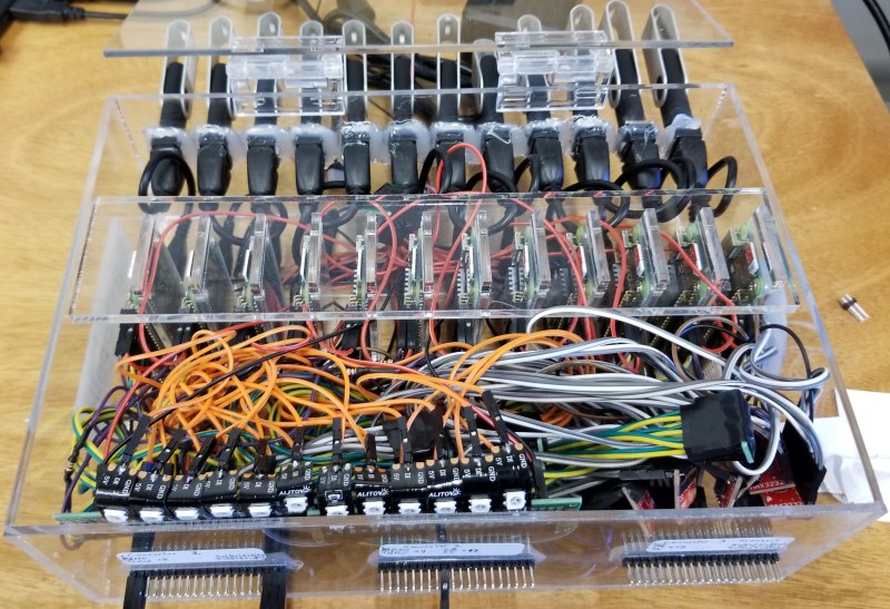
The prototype box contains all the components, wired together in a giant nest with Dupont cables that easily disconnected, in a custom laser-cut and glued acrylic enclosure for extra fragility.

Drawing on the Arduino experience further, the Raspberry Pi process would first program the unit, then verify it was programmed correctly by communicating over the UART, then execute the self-test on the device, which would test the accelerometer, microphone, IR sensors, LED, buzzer, etc, and report back the results and a PASS/FAIL status. We had accomplished our primary goal of removing a significant portion of the process time and cost from the ICT fixture, but we could go further.

Stage Three – Adding Features
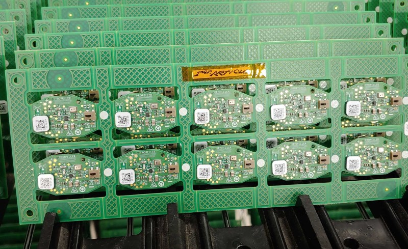
A panel of 10 PCBs with unique MAC address stickers. The MAC address is scanned and programmed into the module.

With the addition of cameras to the fixture, we could read the MAC address on the sticker and use the serial port to program the MAC address into the unit. This allowed us to tie our process to the MAC address that was used to track the unit through the rest of the assembly line.

If you’re wondering why we didn’t pre-assign numbers and then have the operators put on the correct number, it comes down to reducing the chances for operator error. Giving the operator a sheet of stickers and telling them to put them on the units is way less error-prone than having them put specific stickers on specific units, and faster than printing out barcodes one at a time for individual units.
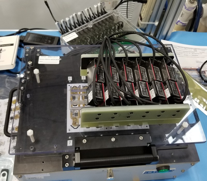
A fixture with 12 cameras for scanning barcodes. Notice the big green button in front of the fixture for starting a cycle.

Next we added the unique key stored on the unit for authenticated communication. The pi generates a 64 byte key, programs and verifies that key on the sensor, then encrypts the key and stores it in the log file. That key gets decrypted on our servers and allows us to communicate with our sensors.

In addition, we added thorough logging; a system log tracks the version numbers of the script, config file, and firmware file, and a separate file logs each cycle with diagnostic data about each stage of the process. These logs are stored on a thumb drive, but also uploaded regularly to a secure FTP so that we can import the logs (and the encrypted keys) immediately, as well as keep tabs on our CM and monitor when they are running our jobs and help them diagnose any problems.

We also made all of this run off a thumb drive. On boot the pi starts a Python script whose sole job is to wait for a thumb drive to be inserted, then run the script on that thumb drive. The thumb drive contains the main Python script, config file, firmware hex file, and logs. This way we have a single box that is completely agnostic to the assembly line, and then we have a dozen thumb drives that stay with the line for that particular device. We don’t need an interface to the pi because we can just plug the thumb drive into a computer to configure it however needed. Anything that makes the job easier for operators makes the assembly line run smoother, and saying “plug these into the back of the box” worked pretty well.

At this point we could program the microcontroller, then execute a self-test, then program the MAC address, and generate a unique key, and output to an LED the status of the process (green for success, yellow for in progress, and red for failure), and save the log to a file. This shaved MINUTES off the cycle time. Before, a panel of 12 was split in two, then each half went through the ICT fixture for 6 minutes, for a total cycle time of around 12 minutes for 12 devices. After the change, we had the full panel of 12 take under a minute, then split and spend under 2 minutes each at ICT. We went from 12 in 12 minutes to 12 in 5 minutes, with more control over the process and greater transparency.

Stage Four – Neptune is Alive
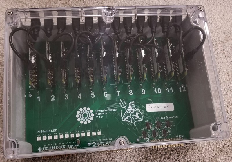
The assembled Neptune box contains 12 Raspberry Pi Zero W, 12 LEDs, 12 USB cables, and cost less than $500 total.

After our first box worked, our CM asked for more so they could service multiple assembly lines, plus have backups and one for test/development. The design was formalized, we found a new enclosure that could be modified easily, and designed a PCB. Total cost for all components is around $500, and the PCBs are easy enough to assemble by hand in a couple hours. We called the project Neptune and the boxes started coming together. Now we have plenty of Neptune boxes, and we have a spec for our fixture developer that allows them to have a very simple circuit they can replicate over and over. Fixtures are rugged beasts that require special knowledge and experience that we don’t have and don’t want to develop, so we outsource that part. The most recent fixture worked immediately with no changes, which is usually nearly impossible.

Stage Five – Changing Cameras

A MAC address sticker is placed on every unit after SMT, but this address must be programmed into the microcontroller itself. To do this, a barcode scanner is used. This is a production environment, and we are packing 12 scanners into a small space, and the scanners must accurately and reliably detect a 2D barcode about 1/2in^2, so not just any scanner will do.

Originally, on the suggestion of our CM, the fixtures were outfitted with Keyence scanners. After we discovered that these are $1400 each, we realized a huge potential for cost reduction. Each of our fixtures has 10-12 devices per panel, so replacing the Keyence scanners with $250 Zebra scanners was an immediate gain. The downside is that our Neptune PCB was designed for RS232 communication with the Keyence scanners using only 2 UART pins, and the Zebra scanners required 5V logic levels with hardware RTS/CTS pins as well. Fortunately we were able to build a cable with an inline circuit that contained an ATtiny84 for each of the cameras.
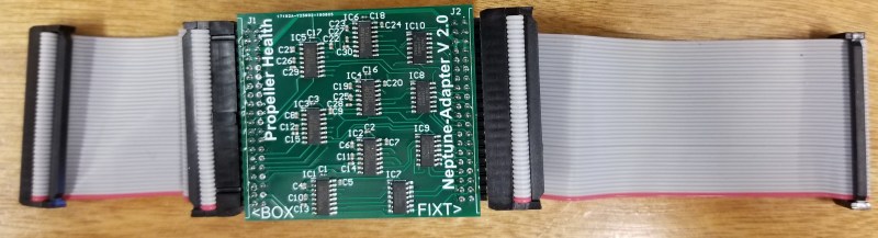
The adapter converts RS232 to 5V logic and triggers the Zebra camera.

With a small config file change, we can tell the system to use a slightly different communication protocol. The Pi sends a serial signal, which is stepped up to RS232 inside the Neptune box, then on the cable dongle it steps down to 5V, goes into the ATtiny, where it is parsed, and if the desired signal then it sends a pulse to the trigger pin of the Zebra scanner, which then scans the barcode and sends the result back to the dongle, where it is stepped up to RS232 and heads back to the unit. The dongle meant that we didn’t have to change anything about the box, and the fixture didn’t have any additional circuitry as well.

Results

The results of Neptune have saved the company a lot of money in fixtures and in unit cost, improved our scalability, given us greater transparency in our production, added features, and made development of new features easier. The Raspberry Pi was instrumental in this, as was OpenOCD. We learned a lot and developed some techniques that would likely be valuable to anyone else doing manufacturing of electronic devices. We’re still working out exactly how we can share this without compromising security or trade secrets, but this is our first step.

The 2010s were a veritable golden age of opening credits in television

Our picks for the decade's best TV main title sequences include <em>Jessica Jones</em>, <em>Star Trek: Discovery</em>, <em>Manhattan</em>, and <em>The Chilling Adventures of Sabrina</em>.

Enlarge / Our picks for the decade's best TV main title sequences include Jessica Jones, Star Trek: Discovery, Manhattan, and The Chilling Adventures of Sabrina. (credit: Collage by Sean Carroll)

The era of peak TV has brought with it a veritable Golden Age of distinctive, innovative main title sequences. So much so, in fact, that there is an entire website, The Art of the Title, devoted to this burgeoning art form, featuring in-depth interviews with the creative people behind all those stunning title sequences. (Fair warning: it's way too easy to lose yourself down the rabbit hole on that site.)

We made a list of our favorite opening credits over the last decade and quickly noticed that two production houses in particular dominated our selections: Imaginary Forces—which produced the main titles for Counterpart, Stranger Things, and Jessica Jones, among others—and Elastic, the creative minds behind the title sequences for Halt and Catch Fire, Masters of Sex, Game of Thrones, and so forth. Along with Prologue (Star Trek: Discovery, Elementary), it's fair to say that these houses have played a major role in shaping the art form over the last ten years.

HBO had already flirted with an artier approach to opening credits with its Emmy-award winning sequence for Six Feet Under in 2001 (produced by Digital Kitchen) and the main title sequence for The Sopranos. "It was the premium networks, like HBO in the late 1990s, that began to set a higher standard for viewer expectations," Alan Williams, a director with Imaginary Forces, told Ars. "TV could be more than just TV. It could be more like film. That type of thinking translated over into other networks."

Read 41 remaining paragraphs | Comments

Image Sensor from Discrete Parts Delivers Glorious 1-Kilopixel Images

Chances are pretty good that you have at least one digital image sensor somewhere close to you at this moment, likely within arm’s reach. The ubiquity of digital cameras is due to how cheap these sensors have become, and how easy they are to integrate into all sorts of devices. So why in the world would someone want to build an image sensor from discrete parts that’s 12,000 times worse than the average smartphone camera? Because, why not?

[Sean Hodgins] originally started this project as a digital pinhole camera, which is why it was called “digiObscura.” The idea was to build a 32×32 array of photosensors and focus light on it using only a pinhole, but that proved optically difficult as the small aperture greatly reduced the amount of light striking the array. The sensor, though, is where the interesting stuff is. [Sean] soldered 1,024 ALS-PT19 surface-mount phototransistors to the custom PCB along with two 32-bit analog multiplexers. The multiplexers are driven by a microcontroller to select each pixel in turn, one row and one column at a time. It takes a full five seconds to scan the array, so taking a picture hearkens back to the long exposures common in the early days of photography. And sure, it’s only a 1-kilopixel image, but it works.

[Sean] has had this project cooking for a while – in fact, the multiplexers he used for the camera came up as a separate project back in 2018. We’re glad to see that he got the rest built, even with the recycled lens he used. One wonders how a 3D-printed lens would work in front of that sensor.

VGA Signal in a Browser Window, Thanks to Reverse Engineering

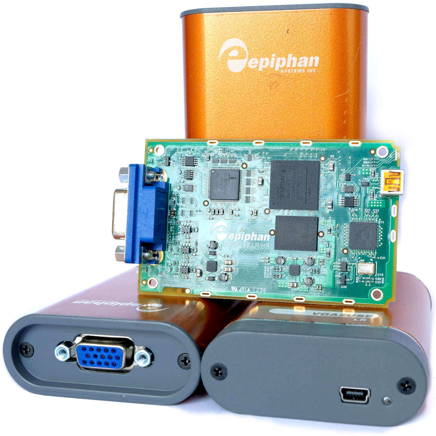
Epiphan VGA2USB LR VGA-to-USB devices

[Ben Cox] found some interesting USB devices on eBay. The Epiphan VGA2USB LR accepts VGA video on one end and presents it as a USB webcam-like video signal on the other. Never have to haul a VGA monitor out again? Sounds good to us! The devices are old and abandoned hardware, but they do claim Linux support, so one BUY button mash later and [Ben] was waiting patiently for them in the mail.

But when they did arrive, the devices didn’t enumerate as a USB UVC video device as expected. The vendor has a custom driver, support for which ended in Linux 4.9 — meaning none of [Ben]’s machines would run it. By now [Ben] was curious about how all this worked and began digging, aiming to create a userspace driver for the device. He was successful, and with his usual detail [Ben] explains not only the process he followed to troubleshoot the problem but also how these devices (and his driver) work. Skip to the end of the project page for the summary, but the whole thing is worth a read.

The resulting driver is not optimized, but will do about 7 fps. [Ben] even rigged up a small web server inside the driver to present a simple interface for the video in a pinch. It can even record its output to a video file, which is awfully handy. The code is available on his GitHub repository, so give it a look and maybe head to eBay for a bit of bargain-hunting of your own.

At Three Grand A Tail Light, There’s An Opportunity For A Hacker

It can be amusing sometimes, to read an incredulous reaction from outside our community to something that would be bread-and-butter in most hackerspaces. Take the sorry saga of the Cadillac XLR tail light, as reported by Jalopnik. This car was a more-expensive Corvette with a bit of lard around its midriff, and could appear a tempting pick for a bit of inexpensive luxury rubber-burning were it not for the revelation that a replacement second-hand tail light for one of these roadsters can set you back as much as three grand. The trusty auto on the drive outside where this is being written cost around a tenth that sum, so what on earth is up? Is it because a Caddy carries some cachet, or is something else at play?

It appears that the problem lies in the light’s design. It’s an LED unit, with surface mount parts and a set of fragile internal PCBs that are coated in something that makes reworking them a challenge. On top of that, the unit is bonded together, and instead of being a traditional on-off tail light it’s a microprocessor-controlled device that gets its orders digitally. This is all too much for XLR owners and for the Jalopnik hacks, who castigate General Motors for woefully inadequate design and bemoan the lack of alternatives to the crazy-expensive lights, but can’t offer an alternative.

Reading about the problem from a hardware hacker perspective they are right to censure the motor manufacturer for an appalling product, but is there really nothing that can be done? Making off-the-shelf microcontroller boards light up LEDs is an elementary introduction project for our community, and having the same boards talk to a car’s computer via CAN is something of a done deal. Add in LED strips and 3D printing to create a new backing for the tail light lens, and instead of something impossibly futuristic, you’re doing nothing that couldn’t be found in hackerspaces five years ago.

So what’s to be learned from the Cadillac XLR tail light? First of all, there’s scope for an enterprising hacker to make a killing on a repair kit for owners faced with a three grand bill. Then, there’s another opportunity for us to be acquainted with the reality that the rest of the world hasn’t quite caught up with repair culture as we might imagine. And finally there’s the hope that a badly designed automotive component might just be the hook by which the issue of designed-in obsolescence moves up the agenda in the public consciousness. After all, there will be other similar stories to come, and only bad publicity is likely to produce a change in behavior.

Of course, to get it really right you need a car that’s hackable in the first place. Or better still, one designed by and for hackers.

Thanks [str-alorman] for the tip.

Cadillac XLR header image:Rudolf Stricker [CC BY-SA 3.0].

The Smart Home Gains An Extra Dimension

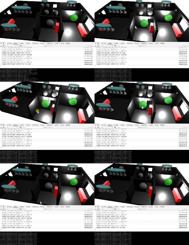
With an ever-growing range of smart-home products available, all with their own hubs, protocols, and APIs, we see a lot of DIY projects (and commercial offerings too) which aim to provide a “single universal interface” to different devices and services. Usually, these projects allow you to control your home using a list of devices, or sometimes a 2D floor plan. [Wassim]’s project aims to take the first steps in providing a 3D interface, by creating an interactive smart-home controller in the browser.

Note: this isn’t just a rendered image of a 3D scene which is static; this is an interactive 3D model which can be orbited and inspected, showing information on lights, heaters, and windows. The project is well documented, and the code can be found on GitHub. The tech works by taking 3D models and animations made in Blender, exporting them using the .glTF format, then visualising them in the browser using three.js. This can then talk to Hue bulbs, power meters, or whatever other devices are required. The technical notes on this project may well be useful for others wanting to use the Blender to three.js/browser workflow, and include a number of interesting demos of isolated small key concepts for the project.

We notice that all the meshes created in Blender are very low-poly; is it possible to easily add subdivision surface modifiers or is it the vertex count deliberately kept low for performance reasons?

This isn’t our first unique home automation interface, we’ve previously written about shAIdes, a pair of AI-enabled glasses that allow you to control your devices just by looking at them. And if you want to roll your own home automation setup, we have plenty of resources. The Hack My House series contains valuable information on using Raspberry Pis in this context, we’ve got information on picking the right sensors, and even enlisting old routers for the cause.

Hackaday Links: December 29, 2019

The retrocomputing crowd will go to great lengths to recreate the computers of yesteryear, and no matter which species of computer is being restored, getting it just right is a badge of honor in the community. The case and keyboard obviously playing a big part in that look, so when a crowdfunding campaign to create new keycaps for the C64 was announced, Commodore fans jumped to fund it. Sadly, more than four years later, the promised keycaps haven’t been delivered. One disappointed backer, Jim Drew, decided he was sick of waiting, so he delved into the world of keycaps injection molding and started his own competing campaign. Jim details his adventures in his Kickstarter campaign, which makes for good reading even if you’re not into Commodore refurbishment. Here’s hoping Jim has better luck than the competition did.

Looking for anonymity in our increasingly surveilled world? You’re not alone, and in fact, we predict facial recognition spoofing products and methods will be a growth industry in the new decade. Aside from the obvious – and often illegal – approach of wearing a mask that blocks most of the features machine learning algorithms use to quantify your face, one now has another option, in the form of a colorful pattern that makes you invisible to the YOLOv2 algorithm. The pattern, which looks like a soft-focus crowd scene rendered in Mardi Gras colors, won’t make the algorithm think you’re someone else, but it will prevent you from being classified as a person. It won’t work with any other AI algorithm, but it’s still an interesting phenomenon.

We saw a great hack come this week about using an RTL-SDR to track down a water leak. Clayton’s water bill suddenly skyrocketed, and he wanted to track down the source. Luckily, his water meter uses the encoder receive-transmit (ERT) protocol on the 900 MHz ISM band to report his usage, so he threw an SDR dongle and rtlamr at the problem. After logging his data, massaging it a bit with some Python code, and graphing water consumption over time, he found that water was being used even when nobody was home. That helped him find the culprit – leaky flap valves in the toilets resulting in a slow drip that ran up the bill. There were probably other ways to attack the problem, but we like this approach just fine.

Are your flex PCBs making you cry? Friend of Hackaday Drew Fustini sent us a tip on teardrop pads to reduce the mechanical stress on traces when the board flexes. The trouble is that KiCad can’t natively create teardrop pads. Thankfully an action plugin makes teardrops a snap. Drew goes into a bit of detail on how the plugin works and shows the results of some test PCBs he made with them. It’s a nice trick to keep in mind for your flexible design work.