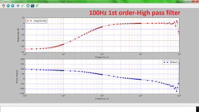
Electrical engineers will recognize the Bode plot as a plot of the frequency response of a system. It displays the frequency on the x-axis and the phase (in degrees) or magnitude (in dB) on the y-axis, making it helpful for understanding a circuit or transfer function in frequency domain analysis.
[Debraj] was able to use a STM32F407 Discovery board to build a Bode analyzer for electronic circuits. The input to the analyzer is a series of sine wave signals with linearly increasing frequency, or chirps, preferably twenty frequencies/decade to keep the frequency range reasonable.

The signals from a DAC are applied to a target filter and the outputs (frequencies obtained) are read back through an ADC. Some calculations on the result reveal how much of the signal is attenuated and its phase, resulting in a Bode plot. The filtering is done through digital signal processing from a microcontroller.
While the signals initially ran through a physical RC-filter, testing the Bode plotter with different circuits made running the signals through a digital filter easier, since it eliminates the need to solder resistors and capacitors onto protoboards. Plotting is done using Python’s matplotlib, with the magnitude and phase of the output determined analytically.
It’s a cool project that highlights some of the capabilities of microcontrollers as a substitute for a pricier vector network analyzer.
No comments:
Post a Comment