Some hacks are born of genius or necessity, and others from our sheer ham-fisted incompetence. This is not a story about the first kind. But it did give me an excuse to show how easy it is to design WiFi-connected devices that work the way you want them to, rather than the way the manufacturer had in mind.
It started out as a sensible idea – consumer electronics in Vietnam have many different electric plug types for mains AC power: A, C, G, F, and I are fairly present, with A and C being most common. For a quick review of what all those look like, this website sums it up nicely. There are universal power adapters available of course, but they tend to fit my most common type (C) poorly, resulting in intermittent power loss whenever you sneeze. So I figured I should replace all the plugs on my devices to be A-type (common to those of you in North America), as it holds well in all the power bar types I have, mainly leftover server PDUs.
This was very straightforward until I got to my desk lamp. Being a fancy Xiaomi smart lamp, they had opted to hide a transformer in the plug with such small dimensions that I failed to notice it. So instead of receiving a balmy 12 volts DC, it received 220 volts AC. With a bright flash and bang, it illuminated my desk one final time.
Sometimes You Just Can’t Let Go
Lamps occupy a curious place in our lives (bringer of light, occupier of desk or table real estate). Perhaps some of you remember the iconic IKEA lamp commercial, and contrary to their advice you did feel sad for the lamp. Luckily, there was a sequel to that story akin to how Hackaday looks at things where a little girl pulled the lamp out of the trash and gave it new life. Today we will be proceeding in a similar lamp restoration vein. Unlike in the video though, we’ll have to replace more than just the bulb!

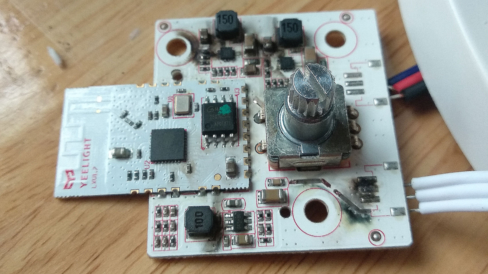
Opening the case revealed the scorched electronics. Besides a small board for the barrel jack, it appears to consist of two high-side LED drivers, a DC-DC converter to step down the 12V input, and a Yeelight-branded ESP module, as well as a combination potentiometer – pushbutton for control.
I never felt the need to install another (potentially data-harvesting) app on my phone just to control a lamp, so had only used the pushbutton so far. A quick search online even found projects that simply remove the WiFi functionality altogether.
Like the authors of those modifications, I liked the design of the lamp, but didn’t trust the WiFi functionality. With those features destructively optimized, I decided to re-implement them, as I had found the physical button on the device a bit cumbersome to use. I only use the lamp while working late on my laptop, so a simple desktop or keyboard shortcut to a Python script would be a convenient way to control it. The base of the lamp contained two large metal plates for ballast, one which could be removed to allow space for my less-miniaturized control circuits without unbalancing the lamp. As usual, I went with an ESP8266 of the Wemos Mini D1 variety, running NodeMCU. The firmware is very standard this time — the default options plus the PWM module.
A Protocol for the NodeMCU Lamp Controller
To minimize complexity, I went with a simple program flow. The ESP8266 turns on, connects to my home WiFi network, then waits for UDP packets on port 10001. When one is received, the first four characters are a device ID, the fifth is the channel (zero or one – cold or warm white LEDs), and the last four characters are the desired brightness from 0-1023.

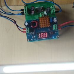
On receiving a valid command, the PWM signals on pins D1 and D2 will be changed as needed. This signal drives a transistor or MOSFET into switching mode. I tested with both transistors and MOSFETs, and it turns out the lamp LEDs require about 20 volts to attain a high brightness, consuming only a low current. As I was out of P-channel semiconductors, I went with a cheap 2N2222 transistor instead of a more expensive 3.3v MOSFET. The use of an N-channel part had an undesirable effect we’ll go into later. To handle power to the ESP8266, and LEDs, I used two cheap generic DC-DC voltage converters in series to provide a 20v and then a 5v line from any DC input from 2-12v.
I started with some simple code to connect to my WiFi network (init.lua), and run program.lua once a connection was established:
wifi.setmode(wifi.STATION)
wifi.setphymode(wifi.PHYMODE_B)
station_cfg={}
station_cfg.ssid="Network Name"
station_cfg.pwd="Network Password"
station_cfg.save=true
wifi.sta.config(station_cfg)

tmr.alarm(1,1000, 1, function() if wifi.sta.getip()==nil then print(" Wait for IP address!") else print("New IP address is "..wifi.sta.getip()) tmr.stop(1)  dofile('program.lua') end end)
The UDP packet control code (program.lua) was simple and passed tests smoothly:
-- Set up two GPIO pins as outputs to be used to control lamp brightness
gpio.mode(1, gpio.OUTPUT)
gpio.mode(2, gpio.OUTPUT)

-- Make sure they start from a known state
gpio.write(1, gpio.LOW)
gpio.write(2, gpio.LOW)

-- Set the pins to work as PWM outputs at 1kHz, 0% duty cycle and start
pwm.setup(1, 1000, 0)
pwm.setup(2, 1000, 0)
pwm.start(1)
pwm.start(2)

-- Listen on port 10001 for UDP packets
port=10001
srv=net.createServer(net.UDP)
srv:on("receive", function(srv, pkt)
    -- When a packet is received, split it into 3 sections. First 4 characters as deviceid, next one as channel, last one as brightness
    print("Command Received")
    deviceid = string.sub(pkt, 1, 4)
    channel = string.sub(pkt, -5, -5)
    brightness = string.sub(pkt, -4)
    -- If deviceid equals device name, change the duty cycle of the selected channel to change the lamp brightness
    if deviceid == 'lamp' then
        print('Lamp command received')
        print(channel)
        print(brightness)
        pwm.setduty(channel, brightness)

    else
        print('invalid data')
        end
   end)
-- Whenever done, go back to listening.
srv:listen(port)
For these tests, I wrote a simple Python script that sends a single packet to set the lamp to a given brightness. It later became an executable script on my laptop, and then an Ubuntu keyboard shortcut. Note your first line below might be different depending on your choice of operating system:
#!/usr/bin/env python
import socket
import time
PORTNUM = 10001

#Broadcast a single UDP packet to all devices on local network containing a 75% brightness command
s = socket.socket(socket.AF_INET, socket.SOCK_DGRAM, 0)
s.setsockopt(socket.SOL_SOCKET, socket.SO_REUSEADDR, 1)
s.setsockopt(socket.SOL_SOCKET, socket.SO_BROADCAST, 1)
data='lamp10750'
s.sendto(data, ('192.168.1.255', PORTNUM))
print data

Switching from High-Side to Low-Side
Now, we get to the troublesome part. The original LED drivers in the lamp used high-side control – that is to say they sit between the power supply and the load (the LEDs) and supply current as needed. This means that our lamp LEDs have 3 cables exposed: two power cables, and a common ground. High-side control can be achieved easily with P-channel semiconductors, but is impractical to do in our case with N-channel parts. N-channel parts are typically used in low-side control: they sit between the load and the ground. For these parts, it would have been better for there to be separate grounds for our LEDs, and a common supply.

What fooled me during breadboarding was that I was actually driving the 2N2222 with a high enough base voltage to allow it to work in a high-side configuration, something I had forgotten was possible and could not trivially replicate in the actual circuit. I had to settle for implementing low-side control with the 2N2222, and leaving one channel of LED lights disconnected for now. This was enough to have a functional lamp, and I can pick up some small P-channel transistors next time I’m in Nhat Tao electronics market to enable both channels.
After cramming all the electronics in where the ballast used to be, I noticed that the case hole where the brightness/color control potentiometer used to be was an exact fit for a female barrel jack. With that addition, the end result looks half decent. I plugged in a 12 volt supply, and everything completely failed to work.
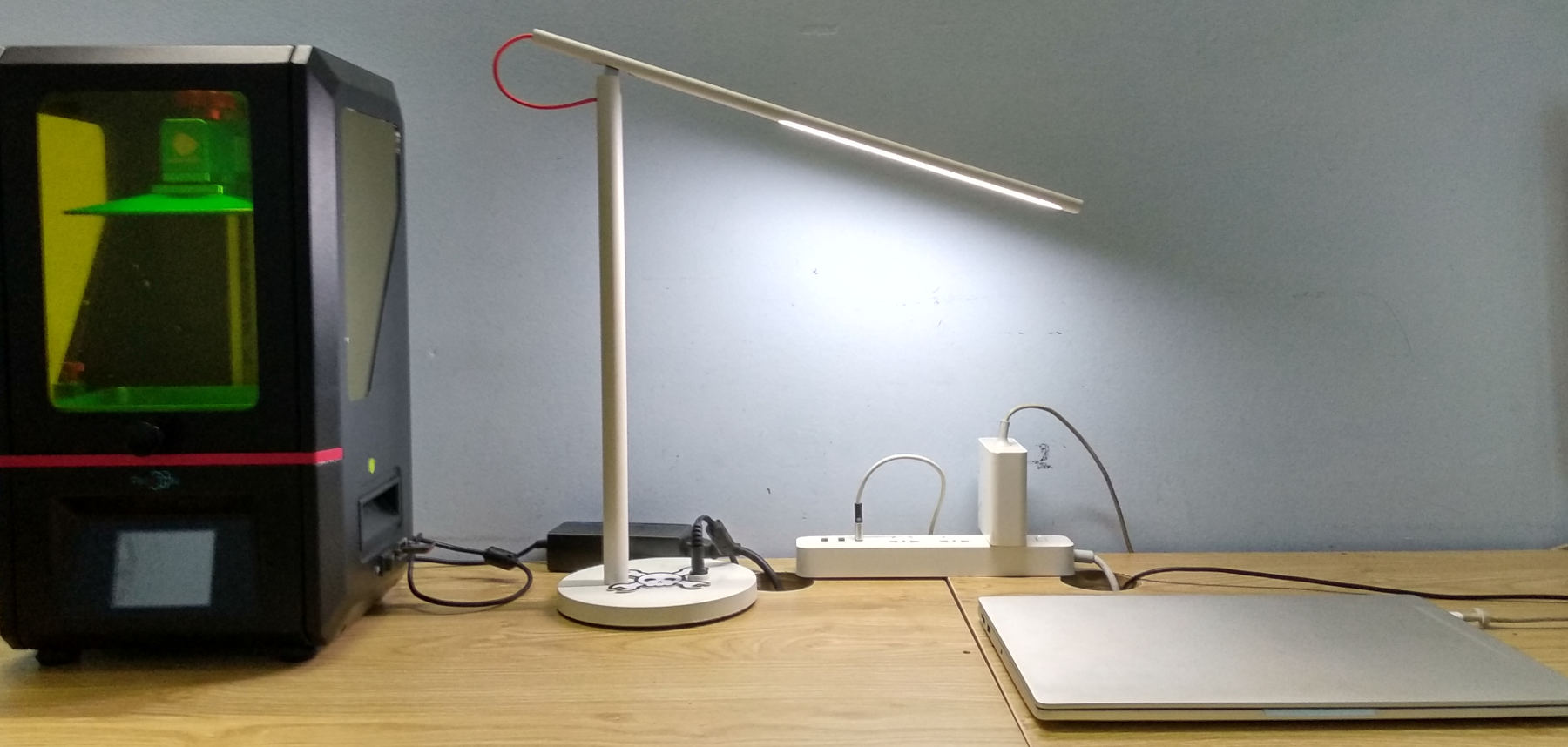
The culprit was again an input voltage that was too high. While rated for 12V input, the step-up converter did not actually tolerate that voltage well, and silently died. After replacing it with a spare and using a 9V adapter instead, faciat lux!

At this point, I could add some type of challenge-response security, but I won’t because it’s a lamp. If you want to travel all the way to my area just to (maliciously?) illuminate my desk, I’ll find you in a short while with my foxhunting gear and we can go grab some dim sum.
I did notice some very minor flickering at the PWM frequency of 1khz, which is the maximum the PWM module allows. It’s possible to attain much higher PWM frequencies using the relatively new but blandly-named PWM2 module. This is especially true when fewer brightness steps are required, e.g. I don’t need 1024 brightness steps for each channel, 16 would be fine. However, I suspect the flickering may be caused by other factors such as the power supply. I’ll tinker with the frequency when I make the upgrade to P-channel transistors and see if it helps. For now, the lamp works well and the control system responds quickly and reliably.
No comments:
Post a Comment