Through the weekend Twitter has been a-titter with news coming out of Saintcon, the annual security conference in Provo, Utah. Now that the weekend is over we can finally get our hands on full hardware and software sources for the curvy, LED-covered badge we’ve been salivating over and a write up by its creators [compukidmike] and [bashNinja]. Let’s dive in and see what’s waiting!
Design
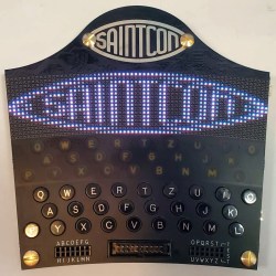
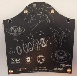
This year’s badge is designed to represent a single tooth on a single rotor of an Enigma machine. The full function of an Enigma machine is quite complex, but an individual device has three rotors with 26 teeth each (one for each letter) as well as a keypad for input and a character display to show each enciphered letter. For reference, the back of the badge has a handy diagram of a badge’s place in the Enigma system.
Reminiscent of the WWII device which the badge design recalls, each unit includes a full QWERTZ keyboard (with labeled keys!) and RGB “lampboard” for individual character output, but unlike the original there’s also a curved 16 x 64 RGB LED display made from those beguiling little ~1mm x 1mm LEDs. All in, the device includes 1051 LEDs! Combined with the unusually non-rectilinear shape of the badge and the Enigma-style Saintcon logo it makes for an attractive, cohesive look.
Tech Specs
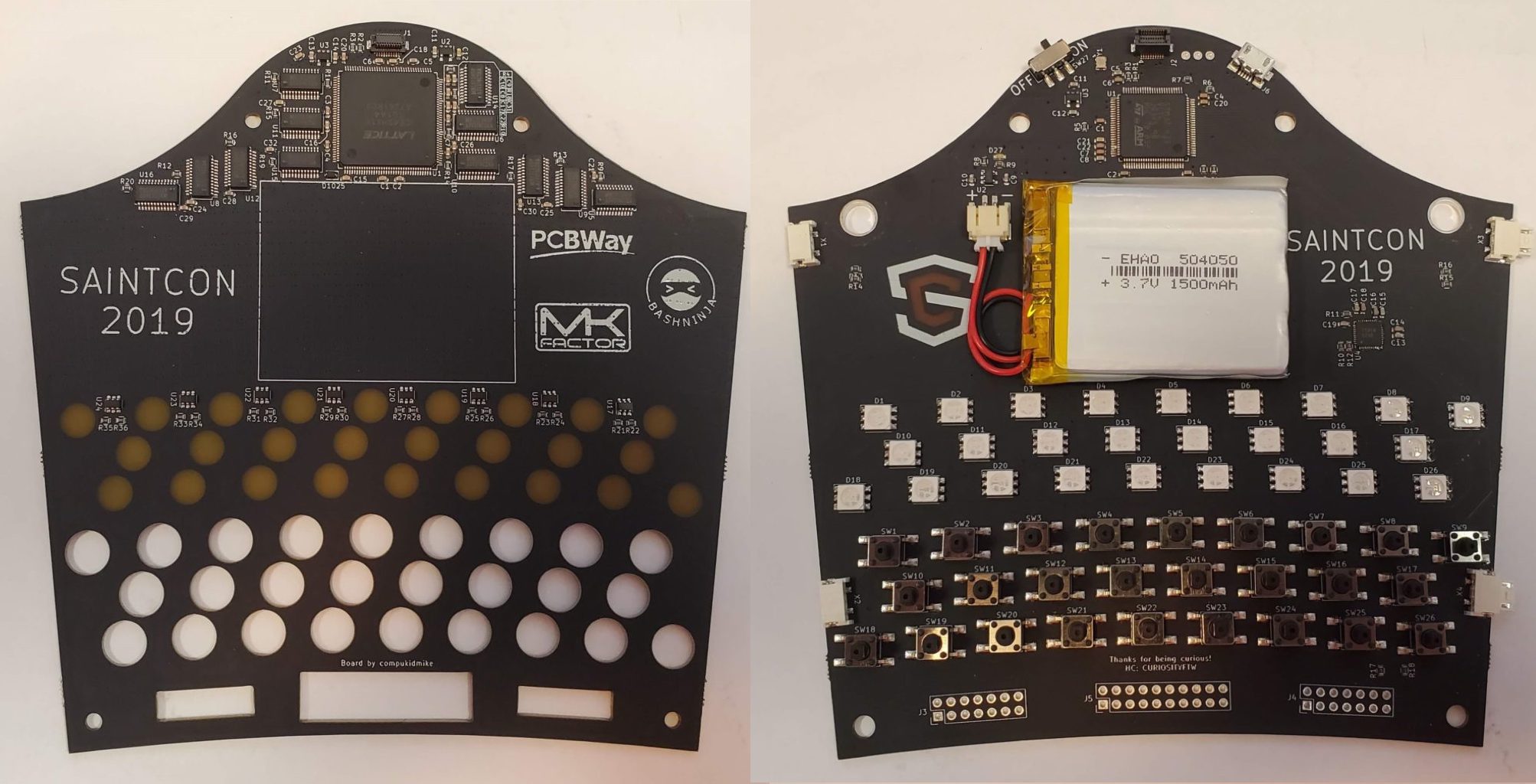
Fortunately for the chiropractic needs of the Saintcon attendees the badge creators opted not to make the chassis out of wood like the original. Instead it’s formed from the increasingly common “sandwich of PCBAs” method, and it’s quite a sandwich indeed! The upper PCBA is mostly dedicated to that delightful RGB display and its supporting hardware. At the top of the image you can see the Lattice ICE40HX1K FPGA and 12 shift registers needed to address the matrix. It looks like they decided that there wasn’t a suitable LED controller which would support so many channels and rolled their own. The FPGA speaks an SPI interface which was designed to be fairly similar to the one used by those big LED matrix panels which have become popular recently, and the system is constrained to updating the display at 30 FPS to avoid LED driver-related ghosting. Of course, you choose an ICE40 FPGA because of its excellent open source toolchain support, and during development Icestudio’s GUI based visual tools were a big help.
The lower PCBA holds the rest of the badge’s magic. The main CPU is a Cortex-M4 based STM32L433 in a 100 pin package. They had been contemplating a smaller part but the features kept creeping until they used every pin! Looking at the design, some of those pin assignments came from the keyboard which was individually connected instead of scanned in a matrix, but even so they did use a controller for the RGB LEDs on the lampboard. All in all the lower board may look more complex, but the more complex schematic is definitely the upper!

But what about those big connectors along the bottom of the badge? In addition to three rotors the original Enigma machine included a plugboard which would swap pairs of letters as the operator pressed them. Of course, in the name of accuracy, the Saintcon badge has a plugboard too! Thus the headers on the sides.
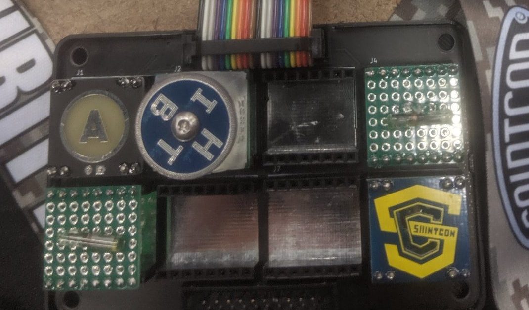
And the middle connector? It wouldn’t be a Saintcon badge without minibadges, so of course that’s for the minibadge adapter! Brian Benchoff may have been off flogging the standards committee to ratify the expanded SAO 1.69bis addon standard in 2019, but back in 2017 [compukidmike] and friends designed the dual header form factor you see here. While an “SAO” only specified a connector, the minibadge standard specifies the entire minibadge, which makes it possible to design holders which display them more like scouting patches to commemorate awards or accomplishments. Different groups and events at Saintcon give out minibadges to display membership or show off achievement, so the badge needed a way to display them.
For a fairly exotic example of what a minibadge can become check out this one we covered recently from [hamster] which drives VFD tubes!
The Badge Challenge
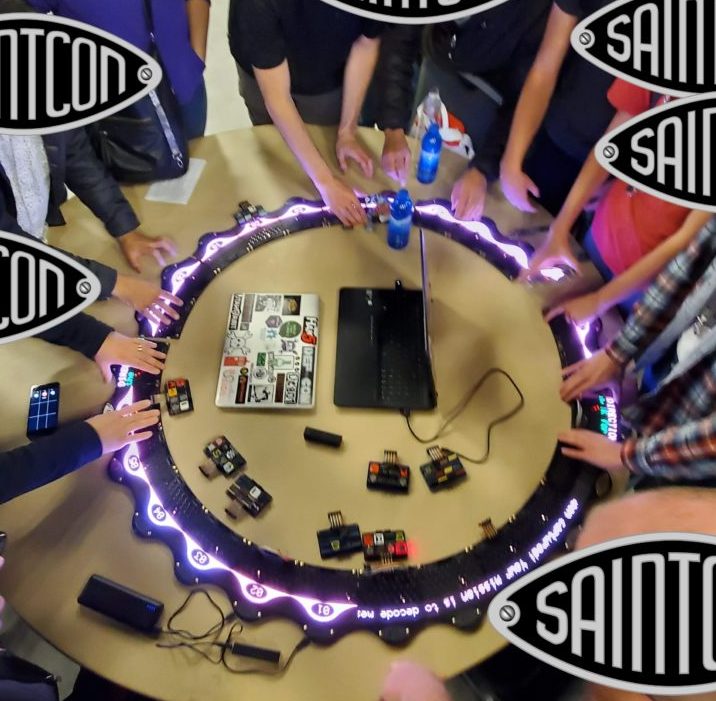
As with many conferences, the Saintcon badge creators included a challenge which was designed to force conference-goers to interact. Everything from the software to the physical shape of the badge encourages this behavior. What do you do with a badge that’s a single tooth of a 26 tooth rotor? Connect it to 25 friends of course!
Each attendee got a set of operating instructions similar to those of a real Enigma machine, and a snippet of enciphered code (with German flavor text of course). By properly configuring their rotor tooth and connecting to other appropriately configured badges, full messages could be deciphered together on the massive 27,326 pixel, 16 x 1664 RGB display.
If you want to make one of these beasts yourself check out the Github repo linked at the top. It includes full hardware, software, and HDL sources for both PCBAs. If you’re thinking of hand assembly we might suggest trying a solder paste stencil; those minuscule LEDs are just begging to be soldered with one.
If (like us!) you enjoy some inside baseball, check out the full write up for details about BOM cost, scope creep, manufacturing, and all your favorite PCBA-related war stories. Overall it sounds like most of the problems were overcome to produce a badge only somewhat over budget, but fully functional for attendees! That sounds like success in our book. This post covered only a fraction of the detail [compukidmike] included in the original, so be sure to take a look at that for more detail.
If the spoken word is more your style, we embedded his badge talk below.
No comments:
Post a Comment