When we make a telephone call in 2020 it is most likely to be made using a smartphone over a cellular or IP-based connection rather than a traditional instrument on a pair of copper wires to an exchange. As we move inexorably towards a wireless world in which the telephone line serves only as a vehicle for broadband Internet, it’s easy to forget the last hundred years or more of telephone technology that led up to the present.
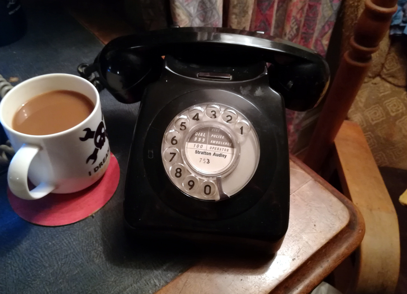
In a manner of speaking though, your telephone wall socket hasn’t forgotten. If you like old phones, you can still have one, and picture yourself in a 1950s movie as you twirl the handset cord round your finger while you speak.
As we move inexorably forward, it’s worth considering for how much longer we’ll be able to do this. If all goes well, I’ll be receiving a new fibre optic connection in a few weeks. Along a sliver of glass will come faster Internet that I can currently dream of, and I’m expecting that the box that our telephone provider puts on the end of it will have a telephone socket that is simply the front-end of a dedicated VOIP client. It’ll undoubtedly work with my digital answerphone, but will it still work with a 50-year old model with an old-fashioned dial designed for use with a mechanical Strowger exchange? If I’m going to have to hack on this old phone, I’d better figure it out now in case I have to hook it up to something else to keep it communicating.
Just How Does A Telephone Work?
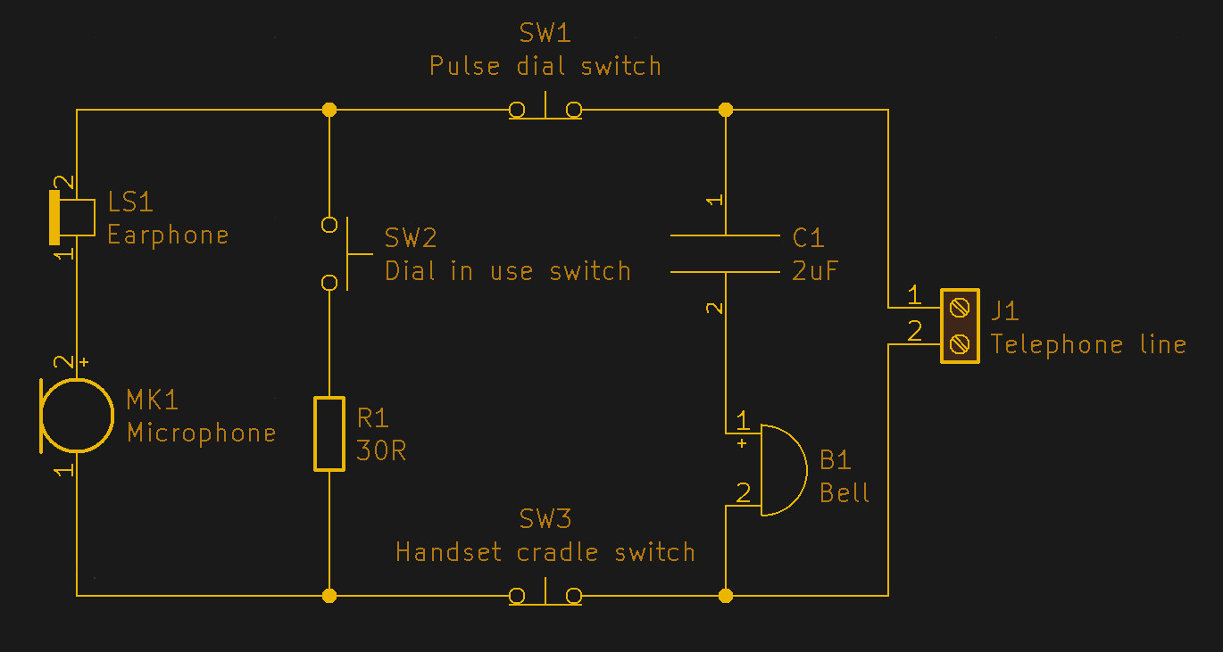
The great thing about a passive device whose roots lie around the turn of the twentieth century is that its principles are relatively easy to understand. A phone like my GPO 746 contains a lot of clever circuitry to give it better audio, and to protect it from line faults, over-voltage, and other mishaps. But its most basic operation can be explained with something like the much-simplified schematic we’ve pictured.
On the left is the handset, with a carbon microphone and an earpiece in series. When the handset is off the cradle, SW3 is closed, and because the line has a standing DC voltage on it a current flows through the handset. Any audio on the line is heard in the earpiece, and any speech into the carbon microphone varies that current and creates an audio signal in return.
![A telephone dial, front and rear. Daderot [CC0]](https://hackaday.com/wp-content/uploads/2019/12/1024px-Automatic_Electric_821C_rotary_dial_-_Telephone_Museum_-_Waltham_Massachusetts_-_DSC08171.jpg)
SW1 and SW2 are the contacts in the dial, and since it has become a viral meme that people below a certain age may be unfamiliar with dial phones it’s worth explaining the operation of the dial for them. A spring loaded disk is rotated to a point representing the desired number by the user before being let go. It returns at a constant rate set by a governor, and as it does so it closes a set of contacts here labelled SW2 to switch in a low resistance across the handset, and it passes its other contacts, SW1, over a toothed wheel. The effect is to interrupt the line current and create a series of pulses set by the number dialed, which were originally used in a mechanical exchange to advance the switchgear a step with each pulse.
An interesting side-effect of this circuit is that with some telephones it was possible to simulate dialing by rapidly depressing the cradle in sequence. On some payphones this offered a means to circumvent the coinbox circuit which disabled the dial. (I remember some students at my university getting into trouble for doing this.) Who needs a 2600 Hz tone to scam the telco!
The Other Side Of The Socket
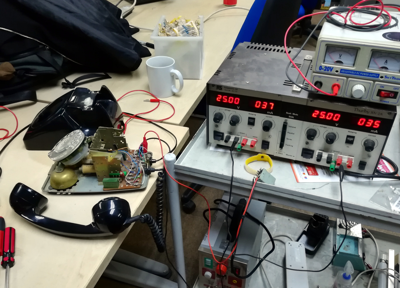
Having understood our telephone, how might we simulate a telephone line to connect it to? I sat down for an evening in the hackerspace with my GPO 746 to find out.
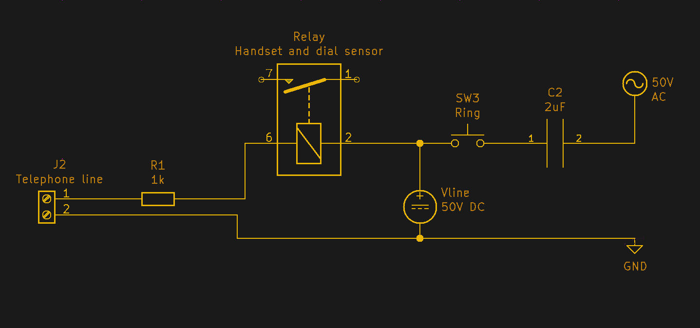
A web search will tell you that a phone line carries a standing DC voltage and an intermittent AC voltage to operate the bell. Further searching reveals that each of those voltages can be 50 V, and that the DC current shouldn’t be more than 50 mA. A good place to start therefore is with a bench power supply set to 50 V, and a 1 kΩ resistor to limit the current and simulate the resistance of several miles of phone cable. With the resistor in place any change to the line can only cause a 50 mA current to flow, and thus the possibility for damage is reduced. Connecting this to the 746 resulted in the sound picked up in the microphone being audible in the earpiece, and had I wanted to I could have retrieved the audio after the 1 kΩ resistor.
Similarly, with the handset on the cradle I could apply an AC voltage and ring the bell. My AC transformer was a bit less than 50 V, but it did work with smaller volume. I still lacked any means of sensing dialing or the cradle, for which I needed to sense the presence or absence of 50 mA DC current. The real GPO exchange back in the day would have done this with a relay in series with the line, so I reached for a small relay. At this point I learned that relays have a hysteresis curve on their close and release currents so it was not as reliable or as quick as I’d hoped. I began to understand why telecoms circuits use reed relays. In the future I’ll have to use a current sensing resistor and a transistor to do the job.
To make this work as a real project, I will have to pay attention to my two 50 V power supplies with probably a little boost converter and oscillator to produce my AC bell drive, and then I’ll need to program a microcontroller to handle being on-hook and off-hook, as well as decoding the pulse streams into numbers. I may also have to pay attention to the phase relationship between my audio source and the audio from the microphone, as feedback can become a problem in some circumstances. Once I have mastered those things I’ll be able to make a unit that sits behind a standard British Telecom master socket and provides a connection to anything I choose, be it a GSM module or a SIP client on a single board computer. In that way I can still be using my GPO 746 dial phone in decades to come.
No comments:
Post a Comment