In the last installment, I told you I was building an open-source, split, ortholinear keyboard called the ErgoDox. I’m doing this because although I totally love my Kinesis Advantage, it has made me want to crack my knuckles and explore the world of split keyboards. Apparently there are several of you who want to do the same, as evidenced by your interest in the I’m Building an ErgoDox! project on IO. Thank you!
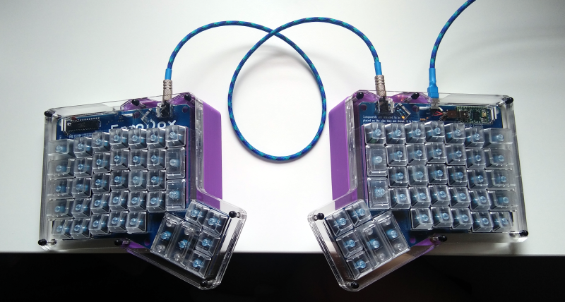
Well boys and girls, the dust has settled, the soldering iron has cooled, and the keycaps are in place. The ErgoDox is built and working. Now that it’s all said and done, let me tell you how it went. Spoiler alert: not great. But I got through it, and it keyboards just like it’s supposed to. I’m gonna lay this journey out as it happened, step by step, so you can live vicariously through my experience.
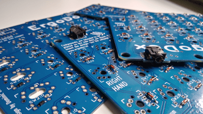
Ode to Diodes
It all starts with the diodes. Every switch gets a diode because of the way keyboard controllers work to detect key presses. When every switch has a diode, there should never be any unintended keystrokes on the screen, a problem known as ghosting. You should also be able to press as many keys as you want at the same time, and they will all register correctly with none missed. If your keyboard does this, it has n-key rollover.
I could have had this keyboard done so much sooner if I had just calmly set aside the SMD diodes that came with my components kit and used through-hole from the start. But no, I had to try soldering 76 of them by hand without solder paste. It went pretty well considering my chisel tip and .32 diameter solder. Continuity checks indicated that I hadn’t managed to fry any of them with heat. But then I started to worry that they just weren’t well-soldered. And why start a build with 152 possible points of failure?
I got through one and half boards worth before I talked myself into switching to through-hole. I’m glad I did, because I don’t mind soldering THT at all, and diodes are cheap in either form. And you know what else? The clear bodies of through-hole diodes just add to the a e s t h e t i c. Yeah, let’s go with that.
Flip. The Boards. Over.
 I wish I could insert siren emoji around this section. Because if you take anything at all away from this story, it should be this part. Remember back in the first post when I said that the PCBs for both halves are exactly the same, and that you use one side for the left hand and one side for the right?
Once the diodes are soldered, it’s of the utmost importance that you flip the boards over and swap them before moving on, because all the other components go on the other side. And I knew this going in. I watched this build video several times before I started, and even wrote down all the steps, including a note about what side of which board the components are supposed to be. And I still messed it up.
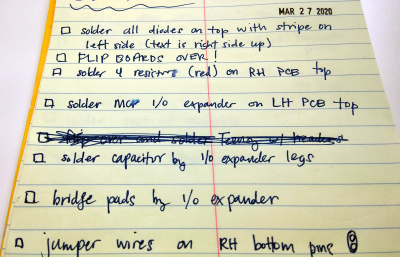
What can I say? I was in soldering mode, and excited to move on from the diodes. It was late at night. My notes with all the steps where I had FLIP BOARDS OVER explicitly written down were in another room, and I was too glued to the chair to get them.
Besides, I’d been over my notes and watched that build video about five times. By the time I realized what I was doing, I’d already soldered all five resistors and both TRRS jacks on the wrong side. The resistors were no big deal, but the TRRS jacks were impossible to desolder without ruining them, or the boards, or both.
So my words of wisdom to you are this: get four pieces of masking or other low-tack tape and label your boards explicitly. Don’t even call them ‘top’ and ‘bottom’, because those designations change. Write something like ‘LH switch insert side’ and ‘LH diode insert side’ to really drive the point home. Do yourself a favor and place these directly over the LEFT HAND and RIGHT HAND labels on the silkscreen.
The Rest of the Components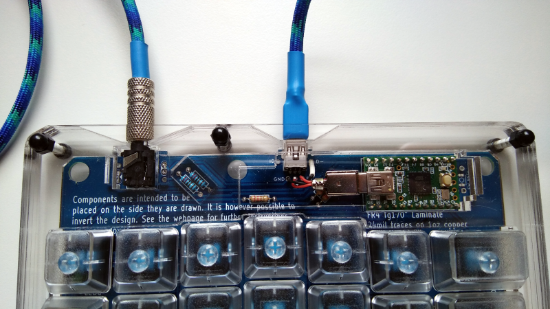
So at this point, I had covered one and a half boards with SMD diodes of questionable utility. When I decided to go through-hole, I de-soldered the half board, cleaned it up, and reused it. After I failed to flip the boards, I had two boards full of THT diodes, each with its TRRS jack on the wrong side. Fortunately, I had a total of five boards to work with when I started. I was now down to the last two.
The rest of the build went pretty well. After the diodes come the five resistors. Then the I/O expansion chip and its little capacitor buddy on the slave side, followed by the TRRS jacks, the Teensy, and the mini-USB extension from the Teensy to the edge of the board. The rest is easy compared to wiring up the mini-USB extender.
Hello, World?
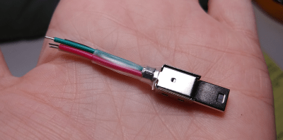
I didn’t expect it to work perfectly the first time, but I thought it would at least do something. In retrospect, I should have done the first test with bona fide USB and TRRS cables, but I was excited about the ones I’d made.
The Teensy should go into blink mode, but it did nothing at all. I had it plugged into a powered USB hub with individual switches for each port, and my first clue was that the port’s light went off when it was supposed to come on. I unplugged the USB extender and found that I must have had the mini-USB diagram rotated 180° or something, because only one of the wires was in the right place.
After I fixed that and switched to a factory-made USB cable, I tried again. Both halves of the keyboard worked, but not for very long. I tried all the mini-USB cables in the house, bought three new ones, and got the same weird results. I also tried different circumstances, like leaving the slave half disconnected, turning off all other HID (I have a lot of HID plugged in) and then bypassing the hub altogether. It still didn’t work reliably.
Unstable Cable
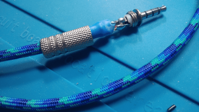
When I finished making the TRRS cable, I tested continuity across the four conductors and everything checked out. One morning I found a mini-USB cable with a ferrite bead and figured, why not try it? I put both halves on the desk, but didn’t connect them together. It worked the first time, so I turned the USB port off and on a couple of times, and yanked and replaced the plug itself a few times for good measure. Every time, the three layer-indicating LEDs came on and it worked fine.
Then I plugged the TRRS cable I made into the master half, and the Teensy rebooted. A-ha! Finally, I decided to go get the only other TRRS I have — the aux cable from my car. When I plugged that one in, the Teensy didn’t react, so I did some more testing. It was at this point that I realized my mistake: not cross-checking all the conductors, as in holding a probe to the tip on one end, and probing both rings and the sleeve of the other end. And that was exactly the problem. After beep testing to confirm, I unscrewed one end of the cable and found three of the four conductors were touching. Making your own cables is fun, but it isn’t easy, and it’s an opportunity to add bugs.
It’s exciting to build tools — you want to keep going because it’s fun, but you also want to be done so you can use the thing. This paradox can lead to problems. There were times I wanted to break the boards in half, but I’m glad I kept at it. Even if I don’t end up using this keyboard much, I have something much better than a standard rectangle to use while I hot rod the Kinesis.
No comments:
Post a Comment