While most people are satisfied with a calculator application on their smartphone these days, there’s still something to be said for the old fashioned desk calculator. Maybe it’s the fact the batteries last long enough that you can’t remember the last time you changed them, or the feel of physical buttons under your fingers. It could even be the fact that it keeps your expensive smartphone from needing to sit out on the workbench. Whatever the reason, it’s not uncommon to see a real-life calculator (or two) wherever solder smoke tends to congregate.
Which is precisely the idea behind this DIY calculator kit. Available from the usual overseas retailers for about $15 USD, it has some hobbyist-oriented features such as the ability to decode resistor color bands, convert hexadecimal numbers, and calculate resistor values for driving LEDs. If you’re going to keep a knock-around calculator on your bench, why not build the thing yourself?
Given the dual nature of this product, a DIY electronics kit and a functional desk calculator for electronic hobbyists, it seems only appropriate to review both aspects of it individually. Which is good, since there may be more to this product than just the sum of its parts.
Kit Review
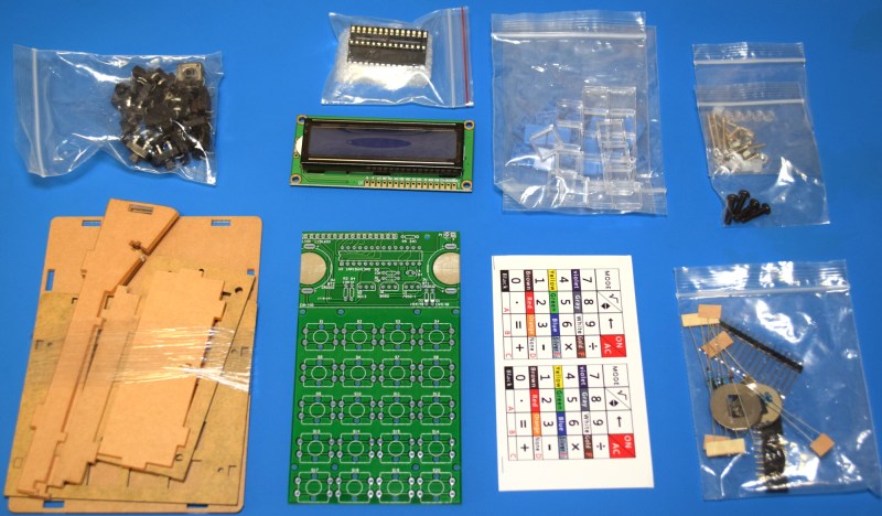
From a hardware standpoint, I was very impressed with this kit. All of the components are separated logically in their own individual bags, and there are even a few spares provided for the resistors, screws, nuts, and standoffs. There are however no spares for the buttons, nor the plastic caps that go over them. This was a bit surprising, as both components are pretty likely to have some damage from transit; several of the buttons in my kit had mangled legs, and at least one of the clear caps had a chunk taken out of it.
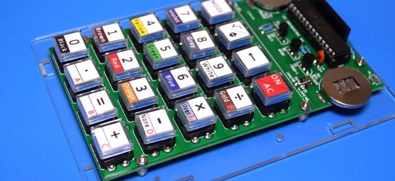
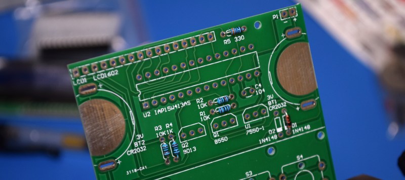
The PCB especially struck me as being of unusually high quality. Anyone who’s imported electronic components from China has likely run into thin and brittle PCBs that you can snap with your fingers, but that’s not the case here. The PCB is substantial, and will have no trouble surviving the physical stress that pushing the buttons will put on it.
In terms of documentation, the kit only comes with a printed circuit diagram and a brief overview of how to operate the calculator’s modes once it’s been assembled. There is however a QR code that takes you to a step-by-step pictorial guide for assembling the calculator. While the average Hackaday reader might not need them, it’s worth mentioning that there are no written assembly instructions that I could find.
Even if you didn’t have the circuit diagram to help you, the silkscreen on the PCB is really quite excellent. It shows the values for all the resistors, part numbers, and the proper orientation for the components that need it. If there’s any pitfall for new players, it will probably be with the installation of the semiconductor devices; there are two different types of transistors and a voltage regulator, all of which are nearly identical externally beyond their part numbers. If you’ve assembled your calculator and it doesn’t work, those are the parts you’ll probably want to double check.
There are, of course, a few sour spots. The laser-cut acrylic enclosure, while it looks very nice when assembled, doesn’t go together very well. The small pockets cut into the plastic to hold the nuts are too large, and I dropped them into the case during assembly more times than I’d like to admit.
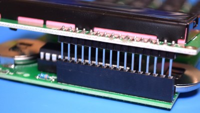 The interconnection between the main PCB and the LCD module also leaves something to be desired. Rather than wires, the kit has you connect the two components with long pin headers.
This would be fine if the boards were to be installed parallel, but to fit inside the enclosure, the LCD needs to be at an angle. Bending the pins is a fiddly operation, and took a few attempts to get right. Not a huge deal, but it does seem like an oversight considering how well the rest of the kit went together.
Calculator Review
While the hardware was a pleasant surprise considering how cheap the kit was, the software is another matter entirely. For one thing, there are annoying glitches throughout. Such as characters disappearing from the display, or the fact that only some buttons seem to be registered by the calculator’s inactivity timer. Several times the device has turned off while I was using it, apparently because I had been shuffling through modes instead of entering numbers.
While it might not be a problem in day-to-day usage, one of the biggest surprises to me was that I could only enter in 7 digits. This seems an arbitrary limitation on a 16×2 display, especially when the answers can be longer.

Although, not much longer apparently. If you try to calculate too large of a number, it will quite literally tell you that it can’t do it. We’re not even talking scientific notation stuff here, even numbers in the tens of millions are beyond this device.

On the subject of the firmware, I was also disappointed to find that there doesn’t appear to be a public release of either the code or binary that the calculator’s STC IAP15W413AS microcontroller is running. On a DIY kit with a socketed MCU, you’d think there would be at least some provision for updating or modifying the firmware. Though to be fair, nothing it the kit’s documentation or marketing lead me to believe this would be the case.
Beyond the firmware and usability issues, the enclosure of the calculator is designed in such a way that changing the batteries would require the entire kit be disassembled. Seriously, you’d have to take the whole case apart and remove the PCB from it just to pull the two coin cells out. Perhaps that’s the reason for the calculator’s incredibly aggressive automatic power off feature.
Hacking Possibilities
While the out-of-the-box experience might not be too hot, we don’t worry too much about such things here at Hackaday. There’s at least one open source project that offers a Reverse Polish Notation (RPN) replacement firmware for this calculator, capable of handling up to 18 digits. This firmware doesn’t include the resistor calculator and hex conversion functions of the original, but anyone looking to turn this kit into a proper tool for mathematics probably won’t mind the trade.
The project goes to great length to document the calculator’s hardware, going as far as to identify compatible components that can be used as drop-in replacements or upgrades. For example, you can replace the original blue-lit LCD with a transflective type that is a bit easier on the eyes. To make the transformation complete, it even includes new cutouts for the calculator’s keys.
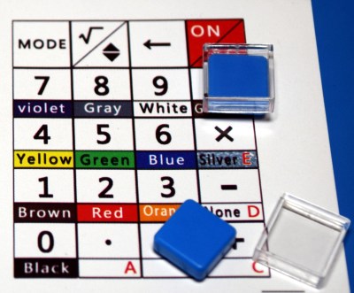
It’s those new key inserts that actually has me the most excited about the possibilities for this calculator kit. Being able to create your own artwork for the buttons allows you to completely customize the device for whatever functions you could need.
That might not be terribly useful if you stick with the STC IAP15W413AS, but what if you ripped that out and replaced it with an ESP8266? With the included wiring diagrams, connecting the key matrix up to the more powerful MCU and the HD44780-compatible LCD would be simple enough.
Now you’ve got the makings of something really special. Perhaps a handheld MQTT home automation controller with custom button art that represents the devices you want to control, or maybe a little macro pad with its own display, perfect for controlling Kerbal Space Program. For the price, it’s a very compelling platform for further hacking that will hopefully start getting more attention.
No comments:
Post a Comment